Shielded connector with insert molded shielding shell and resin cover

a shielding shell and connector technology, applied in the direction of couplings/cases, coupling device connections, line/current collector details, etc., can solve the problem of poor operation efficiency

Inactive Publication Date: 2006-12-12
SUMITOMO WIRING SYST LTD
View PDF10 Cites 13 Cited by
  • Summary
  • Abstract
  • Description
  • Claims
  • Application Information

AI Technical Summary

Benefits of technology

[0008]The housing preferably is molded from resin, and the shielding shell preferably is inserted molded into the housing. Thus, the shielding shell is surrounded at least partly by a unitary matrix of resin. The insert molding achieves fewer assembling steps at an assembling site as compared to a design where a shielding shell is assembled into an already molded housing.
[0009]The connecting means may include a metallic connecting tube that is crimped into connection an end of the shield. The shield is made of a braided wire and is easy to deform. The shield can be connected easily and securely with the shielding shell by securing the end of the shield to the metallic connecting tube.
[0010]The shielding shell preferably has a tubular connecting portion for connection with the connecting tube. The connecting portion of the shielding shell and the connecting tube are connected with their circumferential surfaces placed one over the other. Thus, a large contact area is ensured and no clearance is defined along the longitudinal direction between the shielding shell and the connecting tube to provide stable shielding.
[0011]A cover preferably is mounted on the housing for covering a connecting part of the shielding shell and the connecting means. The cover protects the connecting part of the shielding shell and the connecting means from interference from external matter.
[0016]An insulating short-circuit preventing portion preferably surrounds the wires at a side of the housing inward of the shielding shell. Thus, even if a coating of the wire should be peeled off and exposed, an electrical connection of such a conductor with the shielding shell can be avoided by the contact of the conductor with the short-circuit preventing portion.

Problems solved by technology

Thus the known construction requires several operation steps, and presents poor operational efficiency.

Method used


Image

  • Shielded connector with insert molded shielding shell and resin cover
  • Shielded connector with insert molded shielding shell and resin cover
  • Shielded connector with insert molded shielding shell and resin cover

Examples


first embodiment

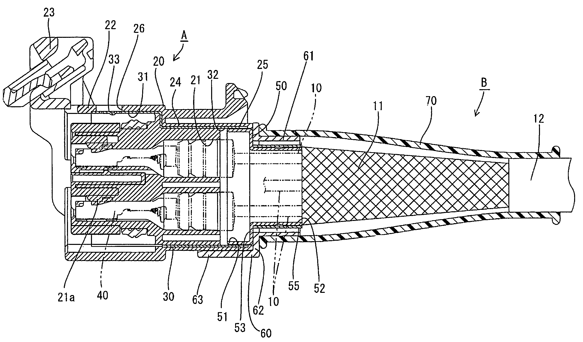
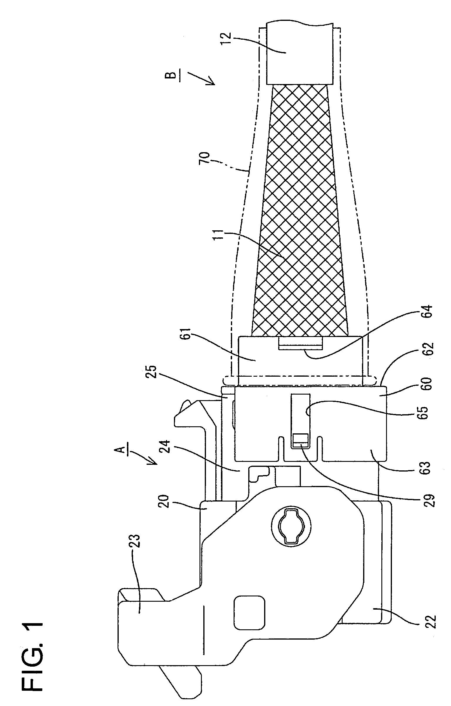
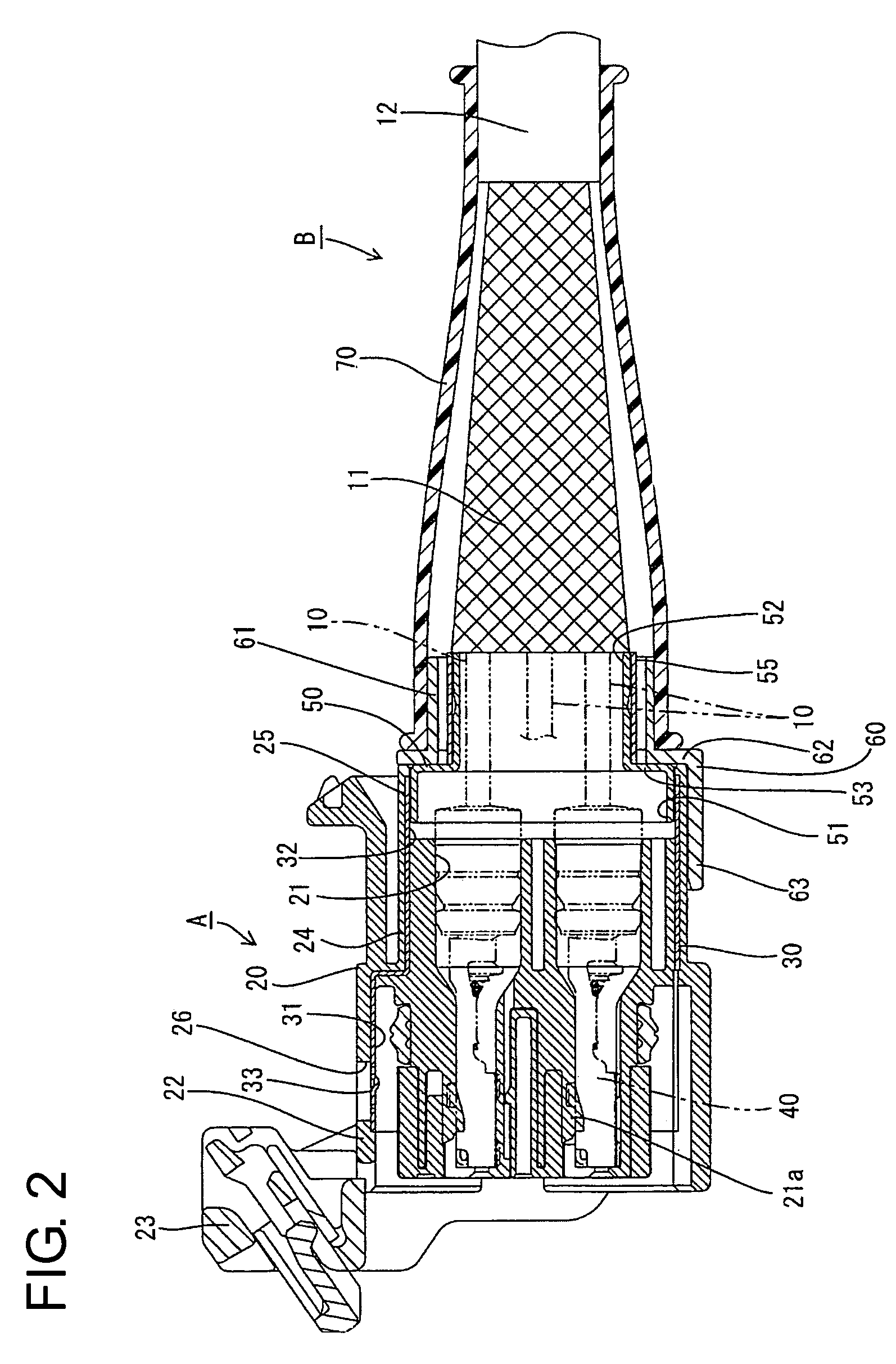
[0043]A shielded connector according to the invention is identified by the letter A in FIGS. 1 to 18. In the following description, the longitudinal direction and forward and backward directions mean the same.

[0044]The shielded connector A is connected with a shielded conductor path B that has wires 10 surrounded by a tubular shield 11. Each wire 10 is a non-shielded wire of known construction with a conductor surrounded by an insulation coating. The shield 11 is formed by braiding fine metal wires into a mesh, and has sufficient flexibility to be extendible both longitudinally and radially. A sheath 12 is mounted on the outer surface of the shield 11.

[0045]The shielded connector A is connected with an end of the shielded conductor path B, and has a synthetic housing 20. Three cavities 21 penetrate the housing 20 in forward and backward directions. A substantially rectangular receptacle 22 is formed at substantially the front half of the housing 20, and a gate-shaped lever 23 is sup...

second embodiment

[0086]In the second embodiment, the first crimping ring may be crimped with the rear end of the shielding jacket fit inside the front end of the shielding member.

fourth embodiment

[0087]In the fourth embodiment, the engaging portion of the housing may be resiliently deformable and the locking portions of the shielding shell may be holes into which the engaging portion is fittable.


PUM


Abstract

A shielded connector (A) has a housing (20) for accommodating terminal fittings (40) connected with ends of wires (10). A metallic shielding shell (30) is provided in the housing (20), and a tubular connecting member (50) connects an end of the shield (11) and the shielding shell (30). Thus, the shielding shell (30) can be connected with grounding members of a mating housing when the housing (20) is connected with the mating housing. Thus, it is not necessary to connect the shield (11) with the grounding members in addition to a connecting operation of the housing (20).

Description

BACKGROUND OF THE INVENTION[0001]1. Field of the Invention[0002]The present invention relates to a shielded connector.[0003]2. Description of the Related Art[0004]Japanese Unexamined Patent Publication No. H08-96919 discloses a known shielded conductor path with a plurality of wires surrounded by a tubular shield made of a braided wire. Terminal fittings are connected with ends of the respective wires and are accommodated in a housing. A cable is formed by twisting an end of the shielding member and is branched off from the conductor path. A grounding terminal then is secured to an end of the branched cable and is connected with a grounding member, such as a body or a piece of equipment.[0005]The above-described construction for branching a grounding circuit from a conductor path requires the connection of a grounding terminal and the connection of the housing with a mating housing. Thus the known construction requires several operation steps, and presents poor operational efficienc...

Claims


Application Information

Patent Timeline
Patent Type & Authority Patents(United States)
IPC IPC(8): H01R9/03H01R9/05H01R13/648H01R13/52H01R13/56H01R13/629H01R13/655H01R13/658H01R13/6583H01R13/6585H01R13/6592H01R43/00
CPCH01R9/032H01R13/6585H01R13/6592H01R13/5219H01R13/62955H01R13/6583H01R13/65912H01R13/648H01R43/00
Inventor WADA, YOSHIMASAWAKATA, SHIGEKAZU
Owner SUMITOMO WIRING SYST LTD
Why Eureka
Try Eureka