Valve device having a long adjustment stroke

a valve device and adjustment stroke technology, applied in the direction of valve details, valve arrangement, operating means/releasing devices, etc., can solve the problems of reducing the precision with which the valve is controlled, requiring much lower positioning precision, etc., and achieves accurate control, reduced cost, and head loss.

Active Publication Date: 2006-12-19
SN DETUDE & DE CONSTR DE MOTEURS DAVIATION S N E C M A
View PDF10 Cites 15 Cited by
  • Summary
  • Abstract
  • Description
  • Claims
  • Application Information

AI Technical Summary

Benefits of technology

[0005]The present invention seeks to remedy the above-mentioned drawbacks and to provide a control valve device that enables head loss to be controlled accurately while minimizing the cost induced by the actuator.
[0007]Thus, a shutter element is provided that has a long adjustment stroke thus requiring much lower positioning precision for the actuator than is the case with present devices, but without reducing the precision with which the valve is controlled. The costs due to the actuator are therefore significantly reduced.
[0008]By means of the structure for the shutter element comprising a skirt with a notch, it is possible to ensure that the fluid flow stream in the duct is completely disengaged when the valve is in the open position, the shutter element then being completely retracted into a portion of the valve which lies outside the flow stream defined by the fluid flow duct. In other words, when the valve is in the open position, the shutter element is retracted completely from the duct so as to eliminate all obstacles in the flow duct and allow the fluid to flow freely without head losses or disturbances due to the presence of a portion of the shutter element in the flow. Consequently, the adjustment capacity of the valve is very large since it can adjust over a range extending from residual leakage past the shutter element when in the closed position, to the duct being fully disengaged when in the open position. The control valve of the present invention thus makes it possible to combine a large adjustment stroke while keeping the advantage of conventional valves having a rotary plug which can be considered as being a tube when in the open position.
[0011]According to a characteristic of the invention, the notch presents a right profile which defines an opening that tapers until it meets the bottom end of the skirt. This makes it possible to obtain a slope for head loss variation that is practically linear with varying angle of the shutter element.
[0014]For space applications, the actuator is preferably slow and irreversible. This presents the advantage of making it possible to allow all or part of a rocket engine to be controlled without requiring dedicated electronics or proportional flight controls.

Problems solved by technology

Thus, a shutter element is provided that has a long adjustment stroke thus requiring much lower positioning precision for the actuator than is the case with present devices, but without reducing the precision with which the valve is controlled.

Method used


Image

  • Valve device having a long adjustment stroke
  • Valve device having a long adjustment stroke
  • Valve device having a long adjustment stroke

Examples


first embodiment

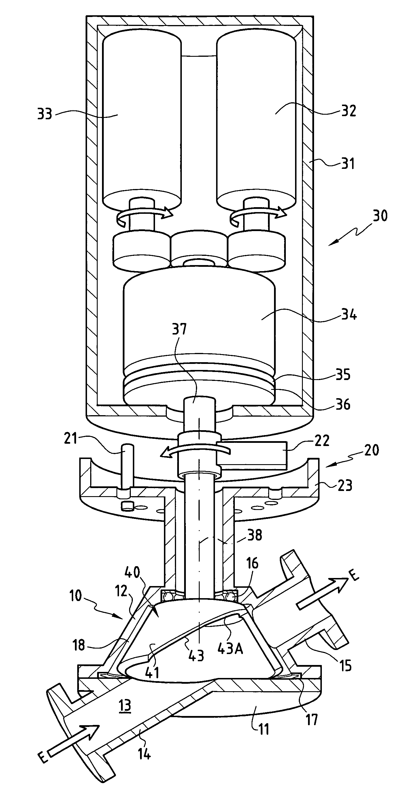
[0027]FIG. 1 shows the invention comprising a control valve device comprising a valve body 10 formed by a bottom body 11 and a top body 12 interconnected in leaktight manner by means of a gasket 17. The bodies 11 and 12 have respective channel portions 14 and 15 defining a fluid flow duct 13 for fluid flowing in a direction E. Each of the channel portions 14 and 15 has a coupling flange to enable the valve device to be inserted in a fluid flow circuit such as a circuit for conveying cryogenic fluid in a rocket engine, for example. The top body 12 includes a cavity 18 for receiving a shutter element 40.

[0028]The shutter element 40 comprises a skirt 41 that is closed in its top portion which is extended by a shoulder (not shown) that bears against a sloping contact ball bearing 16 that takes up both axial and lateral forces. The top portion of the shutter element is connected in its center to a drive shaft 37 for turning the shutter element about an axis 38, which corresponds to the a...

embodiment 50

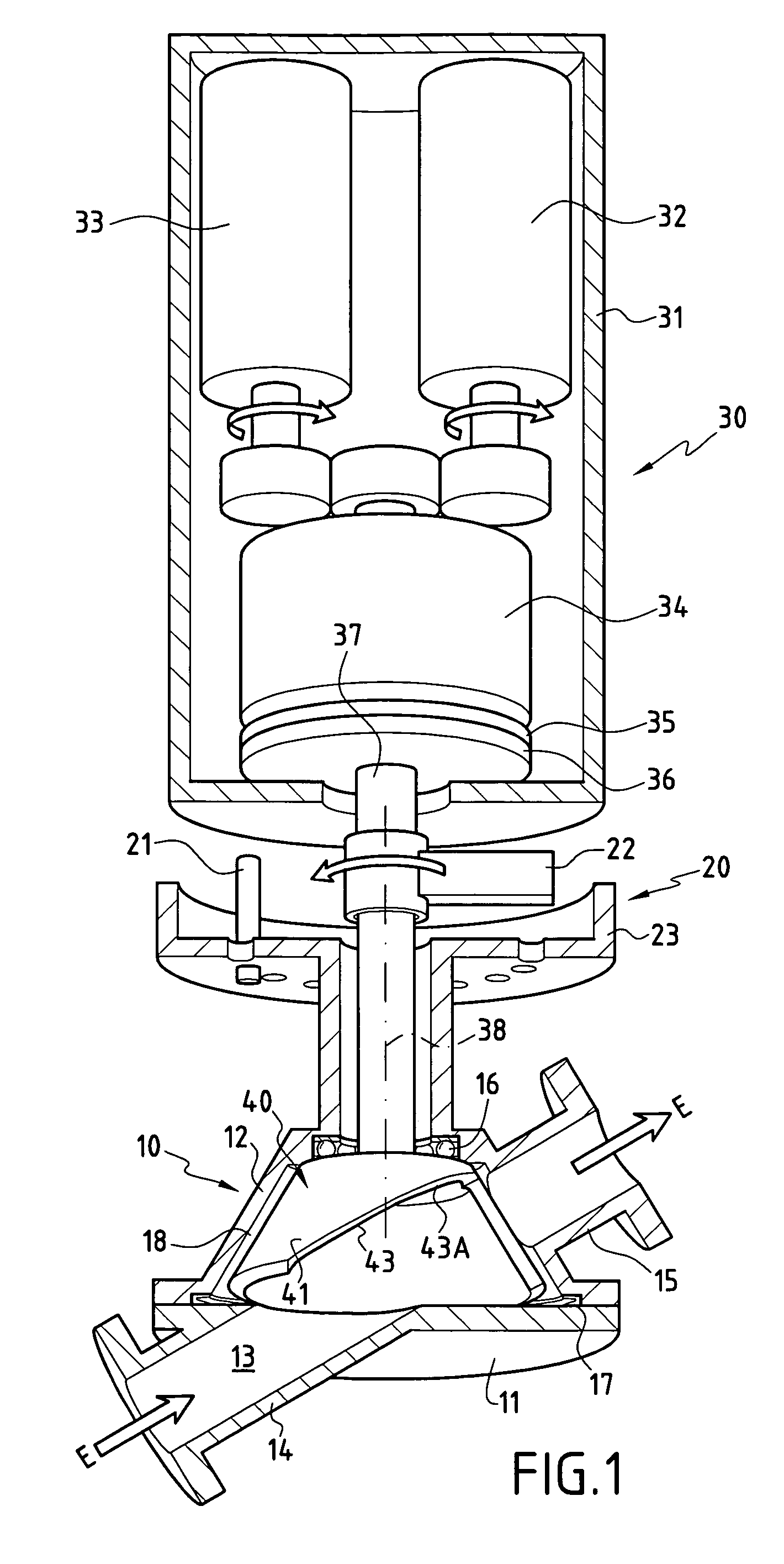
[0030]By way of example, FIG. 2 shows a shutter embodiment 50 whose skirt 51 presents a profile that is not rectilinear, so as to obtain a head loss relationship that is not linear when the shutter element is turned. The notch 53 has an edge 54 of slope that varies so as to present, in a first portion 53A of the notch, a slope that is relatively steep, whereas in a second portion 53B, the edge 54 presents a shallower slope. This makes it possible to obtain a large rise in head loss on turning the shutter element away from the fully-open position. This constitutes merely one example of a variant shape that can be obtained to satisfy some particular head loss relationship. In accordance with the invention, any other type of shape that enables a specific head loss relationship to be defined can be made. For example, it is possible to have a notch whose edge includes crenellations so as to create stepped thresholds in the variation of head loss.

[0031]Another advantageous characteristic ...

third embodiment

[0039]FIG. 4 shows the valve device of the invention. The device comprises a valve body 210 formed by two duct portions 214 and 215 defining an axial duct 213. The top body 212 includes a cylindrical cavity 218 which receives a shutter element 240 comprising a skirt 241 of cylindrical shape. The skirt 241 has a notch 243 that can present dimensions that vary as a function of the desired control stroke. In addition, the notch may present various different shapes depending on the defined head loss relationship, as explained above. In accordance with the invention, the notch 243 is dimensioned so as to enable the skirt 241 to be fully retracted from the duct when in the open position. Thus, in the open position, the duct 213 can be considered as being equivalent to a simple tube, there being no obstacle in the flow stream defined by the duct.

[0040]The shutter element 240 is connected to a drive shaft 237 which is connected to suitable actuator means such as those described above.

[0041]...


PUM


Abstract

The invention provides a control valve device enabling the positioning precision of its abutment to be reduced without reducing the overall control precision of the valve. For this purpose, the valve device comprises a valve body defining a fluid flow duct in which there is disposed a shutter element turned by an actuator by means of a drive shaft. The shutter element is formed by a skirt presenting a notch forming an opening in the wall of the skirt. The notch is shaped in such a manner as to define a variable flow passage in the duct as a function of the angular position of the shutter element between an open position in which the notch co-operates in full with the duct, and a closed position in which said skirt closes the duct.

Description

[0001]This application claims priority to a French application No. 03 08714 filed Jul. 17, 2003.FIELD OF THE INVENTION[0002]The present invention relates to a valve device of the control valve type having a rotary shutter which enables head loss in a fluid flow circuit to be adjusted, e.g. a circuit for feeding cryogenic fluid as is used in a rocket engine. This type of valve is provided with a shutter element which, as a function of its position, varies head loss, and consequently varies the flow rate of fluid along a duct.PRIOR ART[0003]Control valves are control members that are essential for any motor or other device in which the action of a fluid is required. For example, in rocket engines, control valves control the power and internal parameters of the engine. The control performed in such engines by means of valves is to be both accurate and reliable, given the influence it has on the system as a whole. The present solution consists in driving stop or adjustment valves with s...

Claims


Application Information

Patent Timeline
Patent Type & Authority Patents(United States)
IPC IPC(8): F16K31/02F16K5/02F16K5/04F16K31/04
CPCF16K5/0235
Inventor FAYE, OLIVIERPATTYN, JEAN LUCBARRE, WILLIAM
Owner SN DETUDE & DE CONSTR DE MOTEURS DAVIATION S N E C M A
Why Eureka
Try Eureka