
Soccer goal padding

a goal padding and soccer technology, applied in the field of goal padding, can solve the problems of unsatisfactory conventional attempts to address this problem, bulky and unsightly traditional goal padding, and the known source of injury to the participants (e.g., players and officials) of the gam

Inactive Publication Date: 2006-12-19
BISON
View PDF9 Cites 33 Cited by
  • Summary
  • Abstract
  • Description
  • Claims
  • Application Information

AI Technical Summary

Benefits of technology

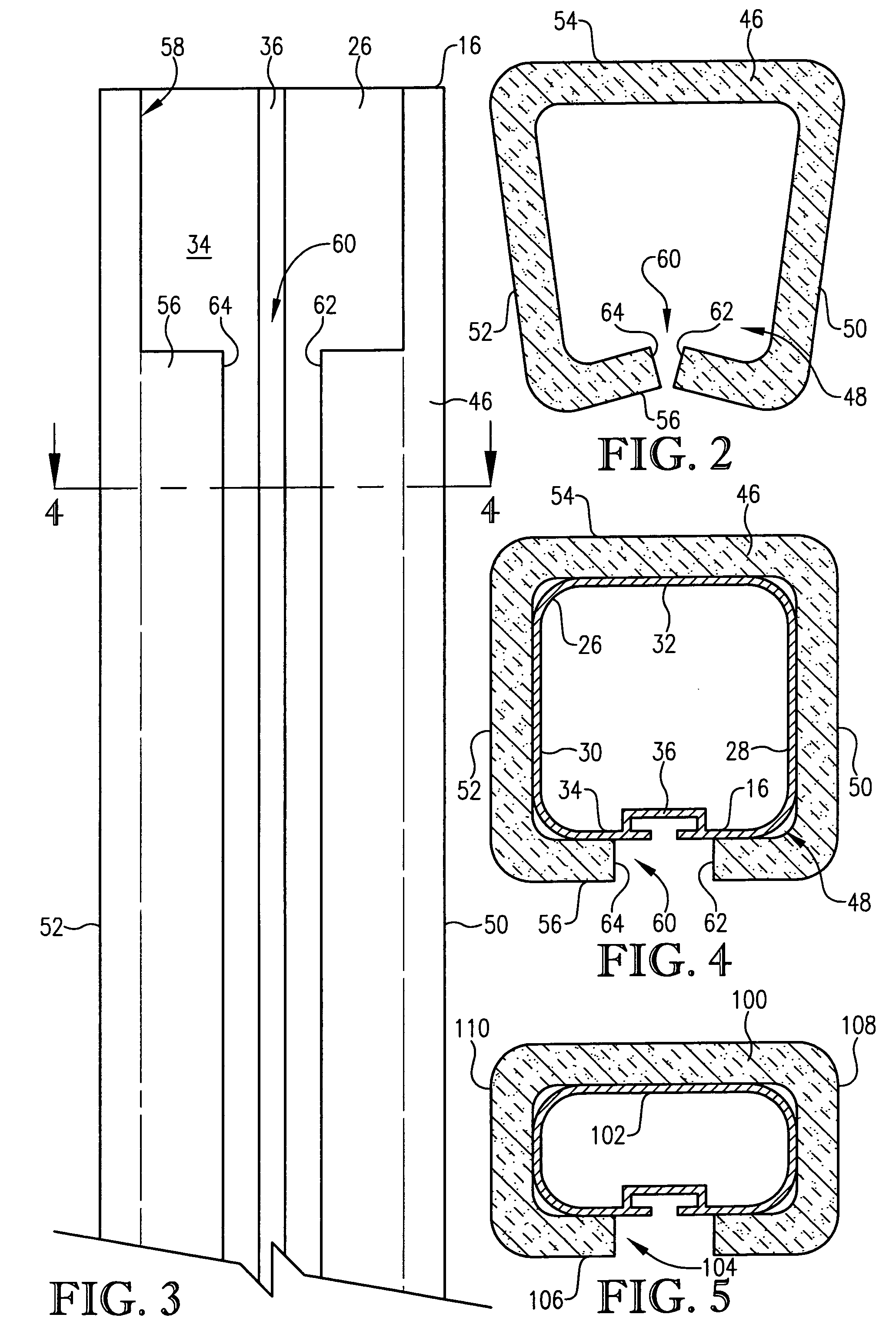
[0010]In addition, an aspect of the present invention concerns a method of forming a goal pad. The method comprises the step of molding a pad preform to an initial preform shape that includes a longitudinally extending slot and a pair of wall sections on opposite sides of the slot. The method further includes the step of, after the molding step and before the final cure time, varying the preform shape so that convergence of the wall sections toward the slot is greater than in the initial preform shape. The varying step includes the step of maintaining the varied shape of the preform until the final cure time.

Problems solved by technology

Soccer goals are known to be a source of injury to participants (e.g., players and officials) of a soccer game.
The goal is typically made of metal (e.g., steel or aluminum) and presents a playing surface that is oriented toward the participants during a game, and impact with the playing surface can cause injury.
Conventional attempts to address this problem are unsatisfactory.
However, traditional goal padding tends to be bulky and unsightly.
Moreover, the manner in which prior art goal padding is secured to a goal post tends to complicate the construction of the padding.
Yet further, conventional goal padding adversely affects the trajectory and speed of a ball rebounding off a padded post (relative to the desired ball rebound).
Although reducing the risk of injury to game participants is imperative, the playing surface of the goal is considered in “play” and any influence on the desired rebound of the ball (the customary and anticipated trajectory and speed of the ball after it has bounced off of the playing surface) is highly undesirable.

Method used


Image

  • Soccer goal padding
  • Soccer goal padding
  • Soccer goal padding

Examples


Embodiment Construction

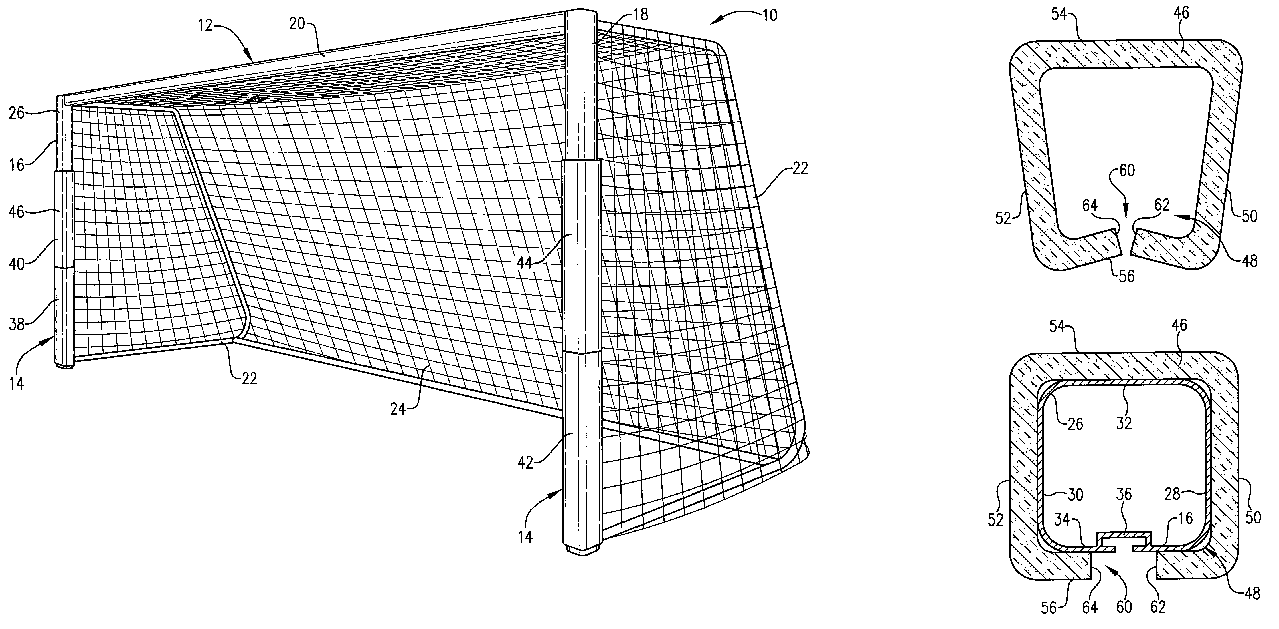
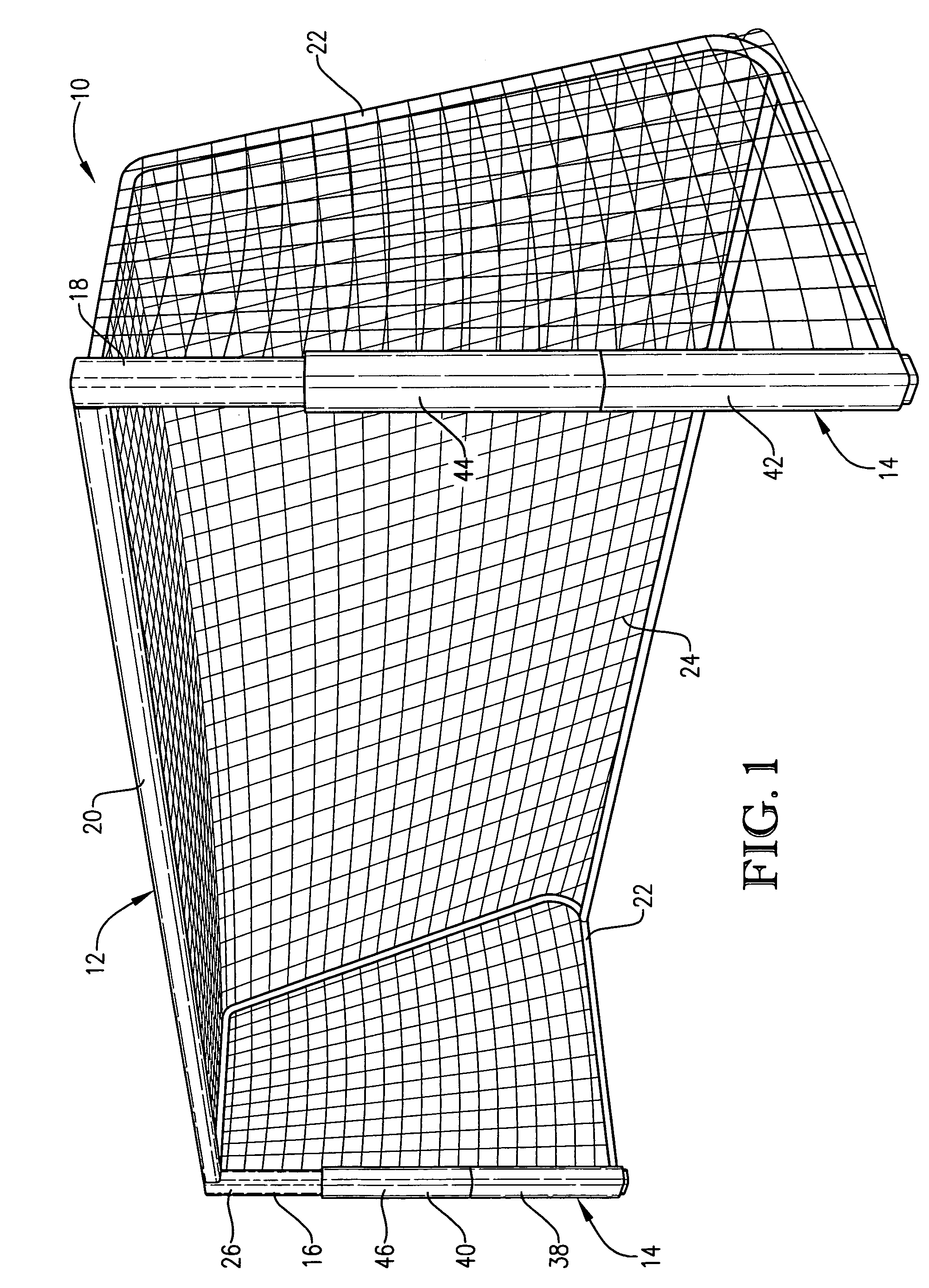
[0021]As shown in FIG. 1, the soccer goal assembly 10 selected for illustration includes a goal 12 and goal padding 14 constructed in accordance with the principles of the present invention. The illustrated goal 12 utilizes one of many conventional designs, and those skilled in the art will appreciate that the inventive padding 14 may be used on various other soccer goal constructions. Furthermore, the principles of the present invention may be used on other athletic equipment (e.g., the pole of a basketball goal assembly).

[0022]Therefore, it shall be sufficient to explain that the illustrated goal 12 includes a pair of spaced apart upright posts 16 and 18 (often referred to as the corner posts) that are preferably vertical in orientation. The illustrated posts 16 and 18 are fixed in the ground, although the principles of the present invention are equally applicable to a portable goal (not shown) having posts that simply rest on the ground. A cross post 20 (often referred to as a cr...


PUM


Abstract

A soccer goal pad comprises an integrally formed foam body for overlying the playing surface of a goal post. The pad is self retained on the post. The goal pad provides impact-cushioning along the playing surface so as to reduce the risk of injury, while minimizing its affect on the trajectory and speed of a soccer goal bouncing off of the padded post. A method of making the goal pad is disclosed.

Description

BACKGROUND OF THE INVENTION[0001]1. Field of the Invention[0002]The present invention relates generally to athletic equipment used in games involving a goal. More particularly, the present invention concerns goal padding that reduces the risk of player injury caused by impact with the goal while maintaining the desired trajectory and speed for balls rebounding off the goal.[0003]2. Discussion of Prior Art[0004]Soccer goals are known to be a source of injury to participants (e.g., players and officials) of a soccer game. The goal is typically made of metal (e.g., steel or aluminum) and presents a playing surface that is oriented toward the participants during a game, and impact with the playing surface can cause injury.[0005]Conventional attempts to address this problem are unsatisfactory. In particular, goal padding has been developed to provide impact cushioning along the playing surface of the goal so as to minimize the risk of injury. However, traditional goal padding tends to be...

Claims


Application Information

Patent Timeline
Patent Type & Authority Patents(United States)
IPC IPC(8): A63B63/00B61G11/12
CPCA63B63/004A63B71/0054
Inventor CUSICK, NICHOLAS J.
Owner BISON
Learn More