
Ratchet extraction wrench

a ratchet and wrench technology, applied in the field of tools, can solve the problems of increasing the complexity of the extraction process, requiring a significant amount of space around the fastener being removed, and the extraction tool may be more difficult to fabricate, so as to achieve a tighter profile and tighter spaces

Inactive Publication Date: 2006-12-26
IRWIN IND TOOL CO
View PDF30 Cites 16 Cited by
  • Summary
  • Abstract
  • Description
  • Claims
  • Application Information

AI Technical Summary

Benefits of technology

"The invention is a combination wrench that has a standard open-type or box-type wrench at one end and a ratcheting extraction box at the other end. The ratcheting extraction box has a fastener extraction head with helically-shaped grooves that bite into the material of the fastener. This design eliminates the need for a separate torque producing tool and makes the wrench suitable for use in tight spaces."

Problems solved by technology

It is well known to use extraction tools to remove threaded fasteners, such as a screw or bolt, that have been damaged to an extent that a standard wrench, screwdriver, alien wrench or other torque producing tool can no longer securely grip the fastener.
For very large fasteners, the extraction tool may be more difficult to fabricate, since it requires a pair of openings machined into the tool whose sizes vary greatly from each other.
Moreover, a significant amount of space surrounding the fastener being removed is required in order to accommodate the extraction tool and separate torque producing tool.
Finally, the need for a separate torque producing tool increases the complexity of the fastener extraction process and requires the user to have available a variety of different sized extraction heads and torque producing tools.

Method used


Image

  • Ratchet extraction wrench
  • Ratchet extraction wrench
  • Ratchet extraction wrench

Examples


Embodiment Construction

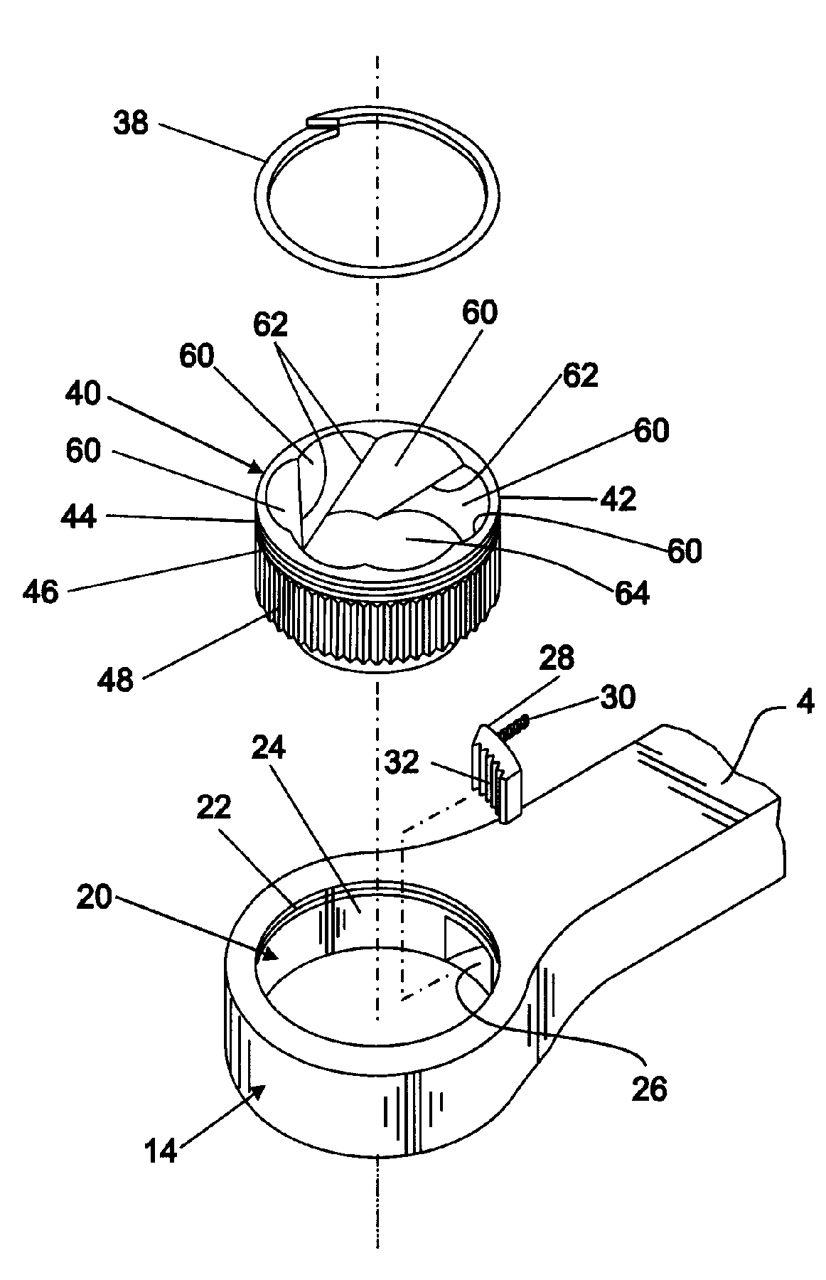
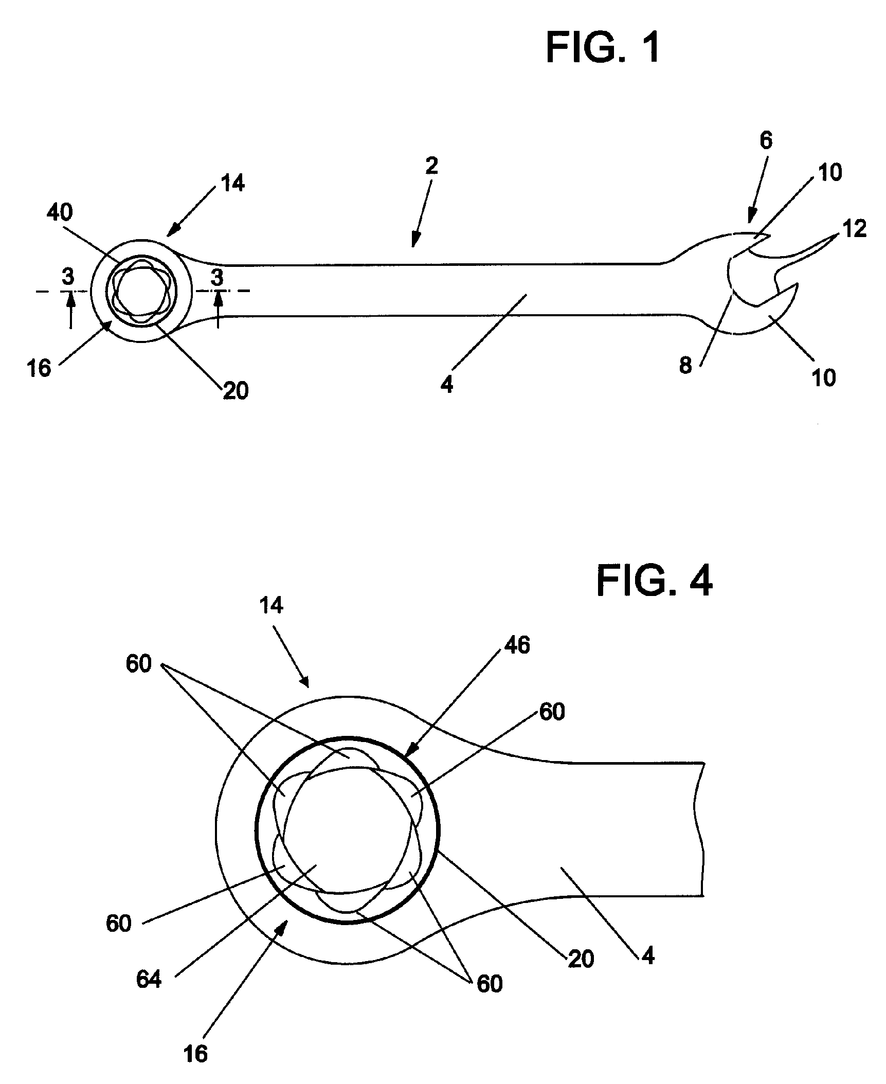
[0014]An embodiment of a ratchet extraction wrench 2 for removing threaded fasteners that have been damaged is shown in FIG. 1. The ratchet extraction wrench 2 consists of a body portion 4 having a first end 6 defining a standard open-type wrench 8 for tightening or loosening threaded fasteners. Open wrench 8 consists of a pair of arms 10 having flat surfaces 12 formed thereon for engaging a fastener. Flat surfaces 12 are spaced from one another a distance to receive and grip a fastener of a predetermined dimension as is known in the art. The wrenches are typically used in sets with each wrench of the set corresponding to a particular standard fastener size. The open-type wrench shown in FIG. 1 may be replaced by a standard box-type wrench where the opening for receiving the fastener is completely enclosed as is known in the art.

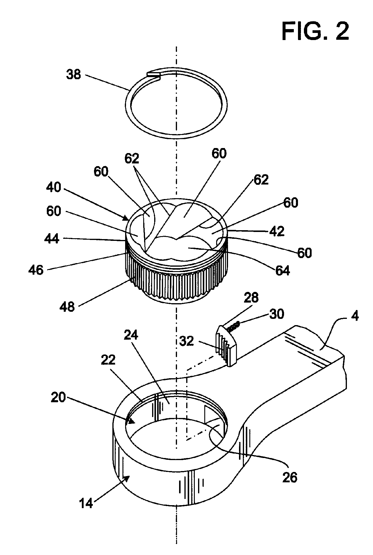
[0015]Body portion 4 has a second end 14 defining a ratchet extraction wrench box 16. As shown in greater detail in FIG. 2, second end 14 defines an apertur...


PUM


Abstract

A combination ratchet wrench having a standard open-type or box-type wrench at one end thereof and a ratcheting extraction box at the other end thereof. The ratchet extraction wrench box is connected by a ratcheting mechanism to the wrench that allows rotation of the ratchet extraction wrench box relative to the wrench only in one direction. The ratchet extraction wrench box is provided with a fastener extraction head that has an interior bore extending inwardly from a receiving end. The bore has a plurality of helically-shaped grooves, each extending from the receiving end and curve radially and inwardly towards the central axis of the bore to form sharp ridges that extend in a helical fashion inside the bore. When the fastener extraction is placed over a fastener head, the ridges “bite” into the material of the fastener. Because the extraction head is formed as an integral part of the wrench there is no need to have a separate turning tool. Because a separate torque producing tool is not required and the wrench has a narrow profile, the extraction wrench can be used in tight spaces.

Description

CROSS-REFERENCE TO RELATED APPLICATIONS[0001]This application claims priority under 35 U.S.C. 119(e) from co-pending provisional patent application Ser. No. 60 / 634,312, filed Dec. 8, 2004, by the inventors hereof, the entire disclosure of which is incorporated herein by reference.BACKGROUND[0002]The present invention relates to tools for turning threaded fasteners such as bolts, nuts, studs, and the like, and more particularly relates to a combination wrench having a ratchet extraction wrench box for removing threaded fasteners that have heads that have been rounded off or otherwise damaged.[0003]It is well known to use extraction tools to remove threaded fasteners, such as a screw or bolt, that have been damaged to an extent that a standard wrench, screwdriver, alien wrench or other torque producing tool can no longer securely grip the fastener. These extraction tools often accomplish the extraction of the fastener through the use of “teeth” made up of angled faces located within a...

Claims


Application Information

Patent Timeline
Patent Type & Authority Patents(United States)
IPC IPC(8): B25B13/50
CPCB25B13/08B25B13/463B25B13/481B25B27/18
Inventor MCCALLEY, JR., RICHARD MICHAELSMITH, ROBIN E.VOGELER, MARK T.
Owner IRWIN IND TOOL CO
Learn More