Reciprocating floor conveyor

a floor conveyor and conveyor technology, applied in the direction of conveyors, transportation and packaging, etc., can solve the problems of cargo contamination, cargo loss, and serious problem of cargo loss

Inactive Publication Date: 2006-12-26
WILKENS MFG
View PDF14 Cites 25 Cited by
  • Summary
  • Abstract
  • Description
  • Claims
  • Application Information

AI Technical Summary

Problems solved by technology

The gaps between adjacent floor slats in reciprocating floor conveyors create two problems.
One problem is the loss of cargo.
Loss of cargo is a serious problem, however, if the cargo is a toxic material or if the cargo is expensive.
The second problem is cargo contamination.
Cargo can be contaminated by water and other material on a road surface that is thrown outwardly by vehicle wheels and passes through spaces between the floor slats.
Cargo contamination is an extremely serious problem if the cargo is for human or animal consumption.
This solution adds weight and expense to reciprocating floor conveyor systems.
Catching material that passes down between the slats also adds disposal problems if it is necessary to dispose of the material that is caught.
This results in a decrease in a gap between some floor slats and an increase in the gap between other floor slats.
This pinching increases the load between the seals and the floor slat surface.
The increased load due to seal compression or due to pinching the seal increases the power required to reciprocate the floor slats and increases wear.
Cold temperatures tend to stiffen resilient seals.
It has been found that some seals that are stiffened by low temperature can wear through the side of a floor slat thereby destroying the floor slat in a relatively short period of time.
Abrasive cargo increases the wear between floor slats and seals that are in sliding contact with each other.
Some parts of floor slats cannot accommodate much wear without the floor slat being essentially destroyed.
The excess force on the seals increases the force required to reciprocate the floor slats and increases wear on the seals and seal contact surfaces.
The solids held by the frozen liquids also increase wear on the floor slats and the seals if the solids are abrasive.

Method used


Image

  • Reciprocating floor conveyor
  • Reciprocating floor conveyor
  • Reciprocating floor conveyor

Examples


Embodiment Construction

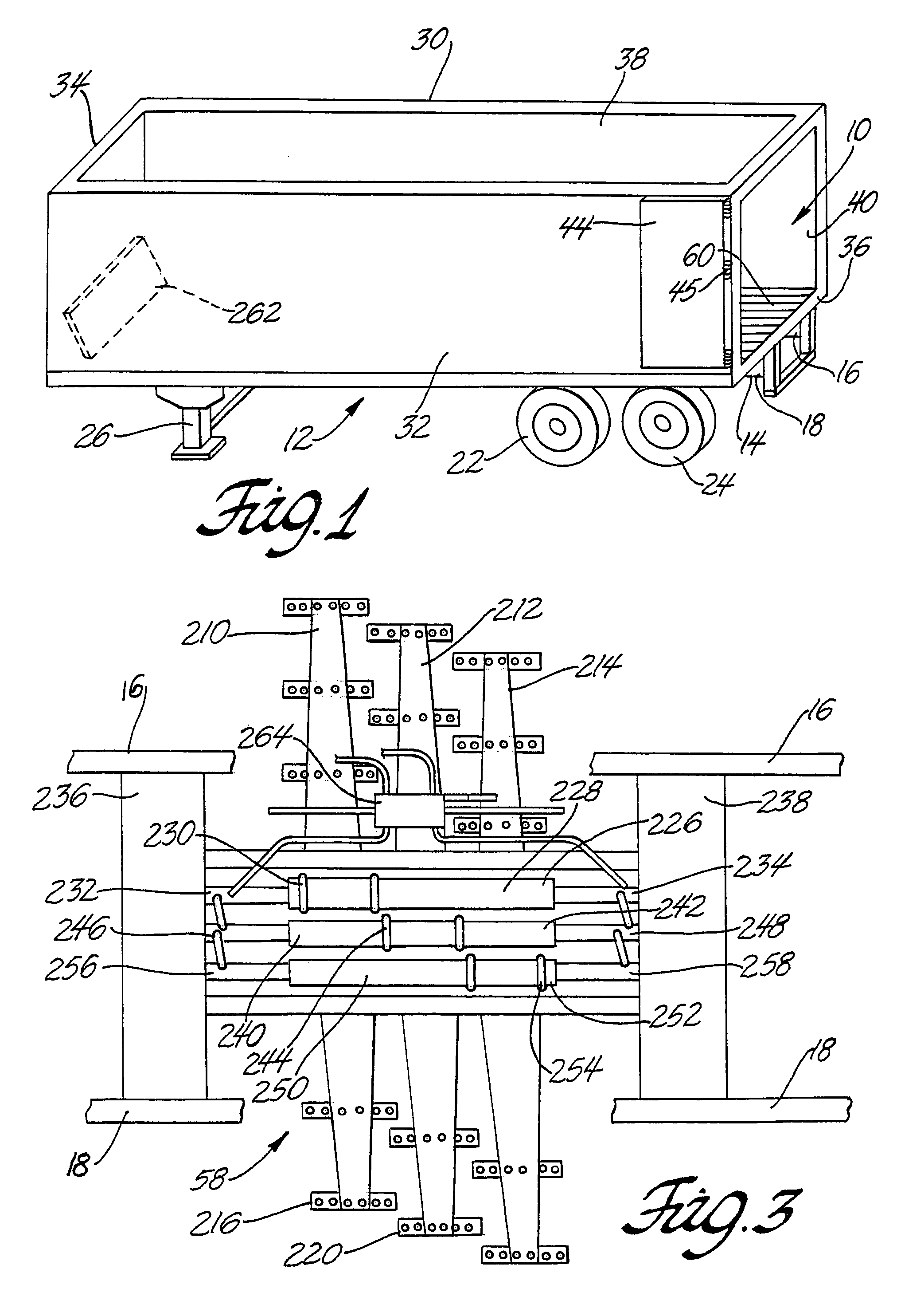
[0027]The reciprocating floor conveyor 10 is shown in the drawing as part of a semi trailer 12. The reciprocating floor conveyor 10 could also be part of a van body mounted on a truck chassis. The floor conveyor 10 may also be part of a stationary conveying system. The semi trailer 12 as shown in FIG. 1 has a main frame 14 which includes a pair of spaced apart channel members 16 and 18 that are parallel to a center axis 20 running the length of the semi trailer. The rear portion of the semi trailer 12 is supported by wheels and tires 22 and 24 that are rotatably journaled on conventional axles. The axles are attached to the main frame 14 by a suspension system. A portion of the semi trailer 12 is supported by a vertically adjustable landing gear 26. A hitch pin (not shown) for attaching the semi trailer 12 to a fifth wheel on a tractor is attached to the bottom by the main frame 14 on the center line 20 of the semi trailer 12 forward of the landing gear 26. Channel members 16 and 18...


PUM


Abstract

Reciprocating floor conveyor include floor slats and slide bearings. The floor slats include a top section, first and second side walls that extend downward from the top section, a first bottom flange integral with the first side wall and a second bottom flange integral with a second side wall. A top section cantilever portion extends laterally outward from the second side wall. A seal flange is integral with the first side wall and includes a seal support surface and a seal flange wall that cooperate with the first side wall to form a seal retainer channel position below the cantilever portion of an adjacent floor slat. The slide bearings have a cross beam, and right and left walls. Wings extend laterally outward from the top of the walls and sit on guide beams.

Description

TECHNICAL FIELD[0001]This invention relates to reciprocating floor conveyors and more particularly to floor conveyors with seals between the floor slats and slide bearings.BACKGROUND OF THE INVENTION[0002]Reciprocating floor conveyors have been used for several years in van bodies and in trailers for unloading cargo. These conveyor systems are widely used for transporting bulk material such as ground plant material for animal feed, saw dust, wood chips, bark and plant material for human consumption. The conveyor systems include a plurality of parallel floor slats each of which extends substantially the length of the van body or trailer on which it is mounted. Each floor slat is supported by two slide bearings that permit it to slide back and forth in a direction parallel to its long axis.[0003]Several different drives and drive systems have been employed in reciprocating floor conveyors to reciprocate the floor slats back and forth. A commonly used drive system includes three hydrau...

Claims


Application Information

Patent Timeline
Patent Type & Authority Patents(United States)
IPC IPC(8): B65G25/04B65G25/06
CPCB65G25/065
Inventor WILKENS, ARTHUR L.ALDRIDGE, JR., MICHAEL A.DAMROW, RODNEY D.
Owner WILKENS MFG
Why Eureka
Try Eureka