Method of constructing an optical transmission line and an optical transmission line

Inactive Publication Date: 2006-12-26
SUMITOMO ELECTRIC IND LTD
View PDF3 Cites 11 Cited by
  • Summary
  • Abstract
  • Description
  • Claims
  • Application Information

AI Technical Summary

Benefits of technology

[0006]In order to overcome the problem mentioned above, it is an object of the present invention to provide a method which can easily connect a plurality of opti

Problems solved by technology

When constructing an optical transmission line by connecting a plurality of optical fibers differing from each other in terms of a transmission characteristic such as chromatic dispersion, it is not easy to determine whether or not the optical fibers to be connected can const

Method used


Image

  • Method of constructing an optical transmission line and an optical transmission line
  • Method of constructing an optical transmission line and an optical transmission line
  • Method of constructing an optical transmission line and an optical transmission line

Examples


Embodiment Construction

[0025]In the following, embodiments of the present invention will be explained in detail with reference to the accompanying drawings. In the explanation of the drawings, constituents identical to each other will be referred to with numerals identical to each other without repeating their overlapping descriptions.

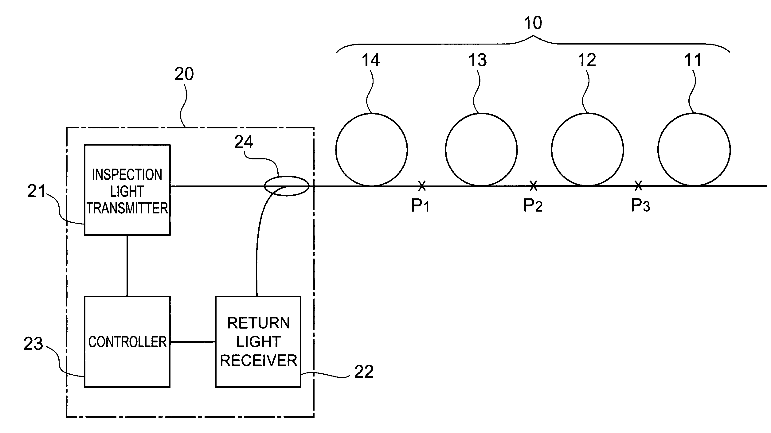
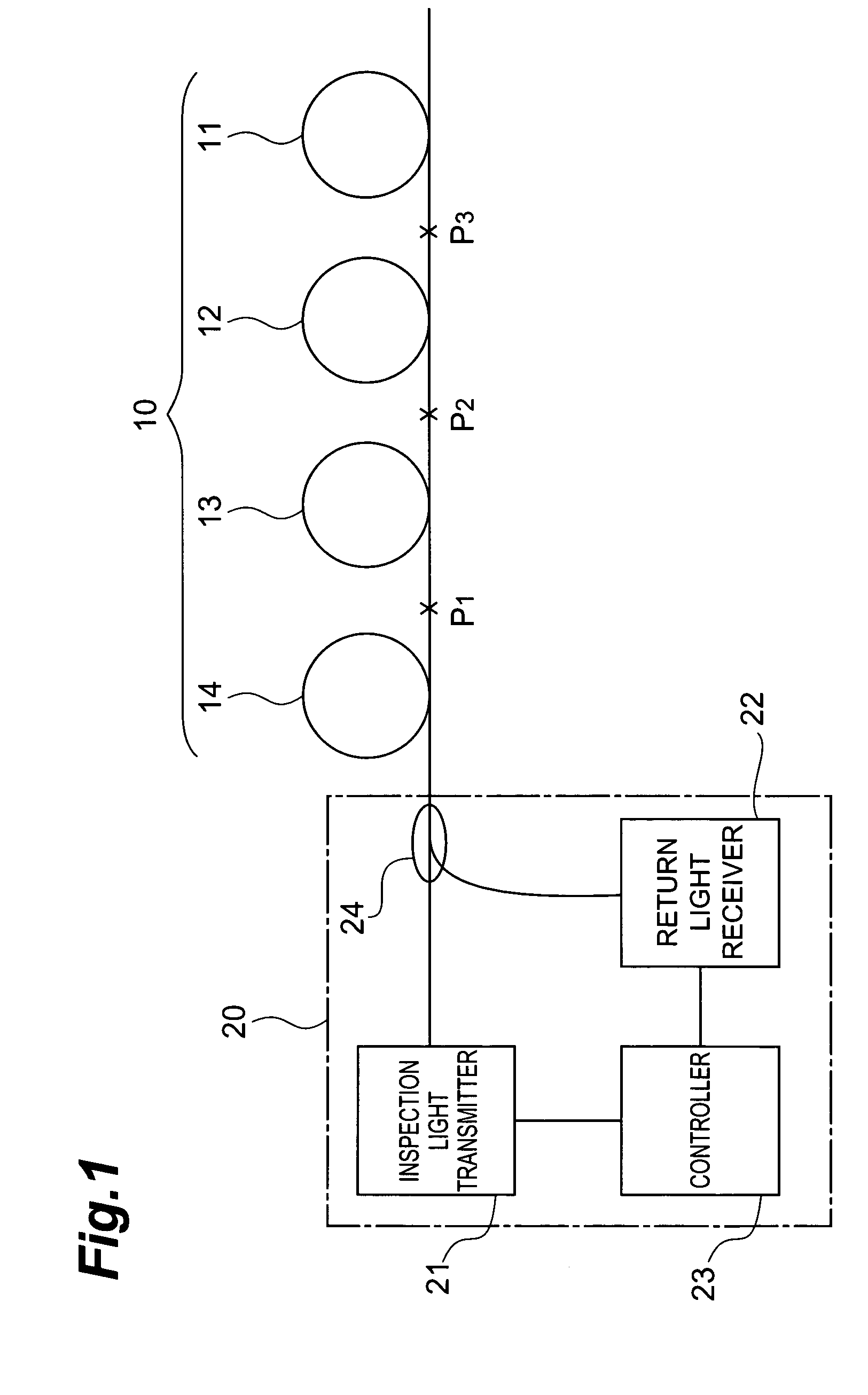
[0026]FIG. 1 is an explanatory view of the optical transmission line constructing method in accordance with an embodiment of the present invention. This drawing shows an optical transmission line 10 to be constructed by the optical transmission line constructing method in accordance with this embodiment, and an OTDR apparatus 20 employed for carrying out the optical transmission line constructing method in accordance with this embodiment. The optical transmission line constructing method encompasses not only a method of connecting optical fibers selected from individual cable groups, so as to construct an optical transmission line having a desirable characteristic; but also ...


PUM


Abstract

The present invention discloses an optical transmission line constructing method comprising the steps of connecting a plurality of optical fibers differing from each other in terms of a transmission characteristic; making inspection light incident on an entrance end of the connected plurality of optical fibers; detecting, on the entrance end side, respective return light components of the inspection light occurring at individual positions of the plurality of optical fibers in its longitudinal direction; evaluating a characteristic information distribution of return light in the longitudinal direction of the plurality of optical fibers; and constructing an optical transmission line according to a result of the evaluation.

Description

BACKGROUND OF THE INVENTION[0001]1. Field of the Invention[0002]The present invention relates to an optical transmission line in which a plurality of optical fibers differing from each other in terms of a transmission characteristic are connected together, and a method of constructing such an optical transmission line.[0003]2. Related Background Art[0004]Optical transmission lines employed as a medium for transmitting signal light in optical communication systems are required to have a small cumulative chromatic dispersion and low nonlinearity in order to restrain the signal light from deteriorating its waveform. Known as one satisfying such a demand is an optical transmission line in which the polarity of chromatic dispersion changes between positive and negative along the longitudinal axis (see, for example, U.S. Pat. No. 6,473,548). A technique for providing the positive and negative chromatic dispersion parts in such an optical transmission line with different colors and marking...

Claims


Application Information

Patent Timeline
IPC IPC(8): G01N21/00H04B10/12G02B6/34G02B6/02H04B10/25H04B10/2525
CPCH04B10/25253G02B6/29376
Inventor SASAOKA, EISUKEONISHI, MASASHIHASEGAWA, TAKEMINISHIMURA, MASAYUKI
Owner SUMITOMO ELECTRIC IND LTD
Why Eureka
Try Eureka