Device plate for mounting a communications device to a raceway

a technology for mounting plates and communications devices, applied in the field of raceways, can solve the problems that the plates used in mounting electrical devices to a raceway do not accommodate the couplers that are normally required with communications devices

Inactive Publication Date: 2006-12-26
THE WIREMOLD CO
View PDF8 Cites 13 Cited by
  • Summary
  • Abstract
  • Description
  • Claims
  • Application Information

AI Technical Summary

Problems solved by technology

Prior art device plates for use in mounting electrical devices to a raceway do not accommodate the couplers that are normally required with communications devices.

Method used


Image

  • Device plate for mounting a communications device to a raceway
  • Device plate for mounting a communications device to a raceway
  • Device plate for mounting a communications device to a raceway

Examples


Embodiment Construction

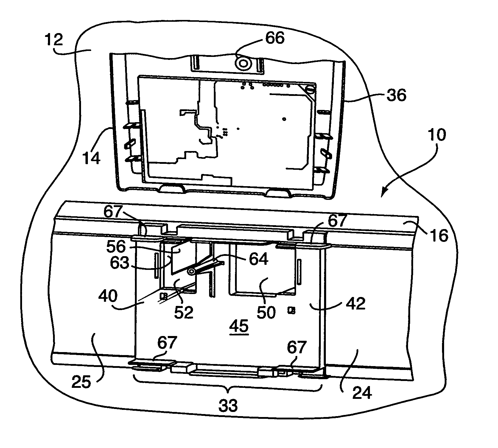
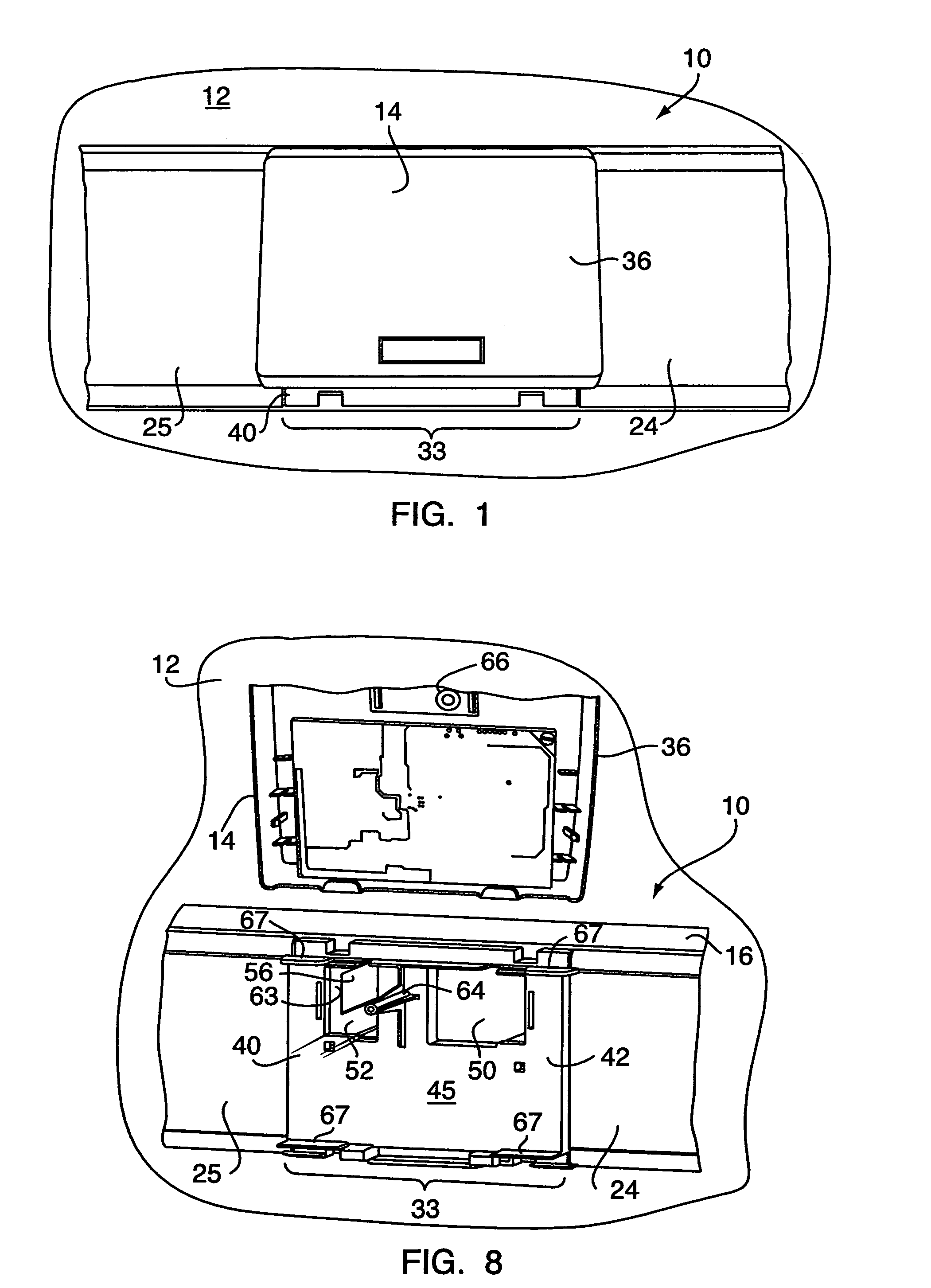
[0022]Referring to FIGS. 1–3, an elongated raceway 10 extends along a wall structure. An Ortronics Wi-Jack™ wireless wall outlet or wireless access point device 14 is shown mounted on the raceway 10. Only a small section of the raceway 10 is shown in the figures, but represents a typical run of Wiremold 5400 style surface raceway. Wiremold and Ortronics are wholly owned subsidiaries of Legrand SNC of Limoges, France.

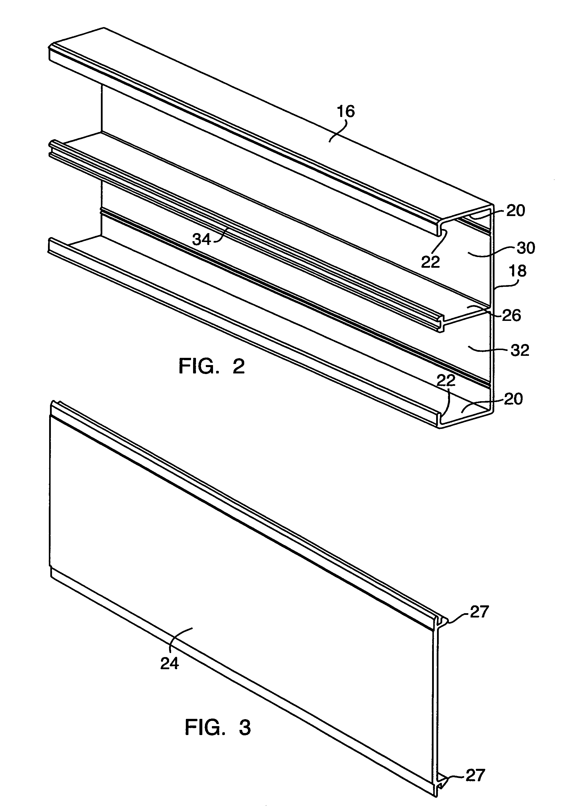
[0023]The raceway 10 includes a generally U-shaped raceway body 16 having a back wall 18 normally mounted to a wall or ceiling structure as shown in FIG. 1. The raceway body 16 includes a pair of opposing side walls 20, 20 extending outwardly from the back wall 18 and generally perpendicular thereto. The side walls 20, 20 extend along the elongated raceway body 16 and each sidewall defines a longitudinal flange 22 at a free edge thereof for coupling a raceway cover panel 24 to the raceway body 16. A divider wall 26 disposed between the side walls 20, 20 also extends gene...


PUM


Abstract

A device plate for mounting a communications device to a raceway defining a wireway, the device plate including a base having first and second opposing sides and defining an opening therethrough for providing access to the wireway when the device plate is attached to the raceway. The device plate being attachable to the raceway such that the first side of the base faces the wireway. The device plate includes a coupler support extending generally perpendicular from the first side of the base adjacent the opening therein such that the coupler support extends into the wireway when the base is attached to the raceway. The coupler support adapted for mounting a coupler thereto. The device plate further including means for attaching the base to the raceway and means for mounting a communications device to the second side of the base.

Description

FIELD OF THE INVENTION[0001]The present invention relates to a raceway used to provide cable along a wall structure, and more particularly to a device plate mountable on the raceway for supporting a wireless communications device.BACKGROUND OF THE INVENTION[0002]Cable raceways are used to support and enclose electrical and communication cables and are typically provided on an existing wall within a structure. The raceway includes a U-shaped raceway body open on one side and mountable to a wall or ceiling structure for enclosing cables to service a work area. Usually the raceway body defines at least one wireway for accommodating power and / or communications cables. Often a longitudinal divider wall is attached to the interior the raceway body such that the raceway body is divided into two wireways which can be used to separate power and communications cables. A bottom wall of the U-shaped raceway body is generally attached to a wall structure along which the raceway extends. Typicall...

Claims


Application Information

Patent Timeline
Patent Type & Authority Patents(United States)
IPC IPC(8): H02G3/08
CPCH02G3/105
Inventor STEMPINSKI, SHAWN
Owner THE WIREMOLD CO
Why Eureka
Try Eureka