Electrophotographic image forming apparatus

a technology of electrophotography and forming apparatus, which is applied in the direction of electrographic process apparatus, instruments, optics, etc., can solve the problems of reducing the space in which the drum shutter must be retracted and difficulty in adjusting the large space of the drum shutter

Inactive Publication Date: 2006-12-26
CANON KK
View PDF36 Cites 164 Cited by
  • Summary
  • Abstract
  • Description
  • Claims
  • Application Information

AI Technical Summary

Benefits of technology

[0008]The present invention solves the above-described problem, and its primary object is to provide an electrophotographic image forming apparatus substantially smaller in size than an electrophotographic image forming apparatus in accordance with the prior art.

Problems solved by technology

In the field of an electrophotographic image forming apparatus, there is a strong desire, in recent years, for a smaller electrophotographic image forming apparatus, creating the problem that it is difficult to allocate a large space for a drum shutter.
In addition, in the case of an electrophotographic full-color image forming apparatus of an inline type, a plurality of process cartridges, different in the color component they develop, must be placed in a limited amount of space, which in turn makes it necessary to place the recording medium conveying portion and fixation station above and below the process cartridges, respectively, exacerbating the restriction regarding the space into which the drum shutter must be retracted.

Method used


Image

  • Electrophotographic image forming apparatus
  • Electrophotographic image forming apparatus
  • Electrophotographic image forming apparatus

Examples


embodiment 2

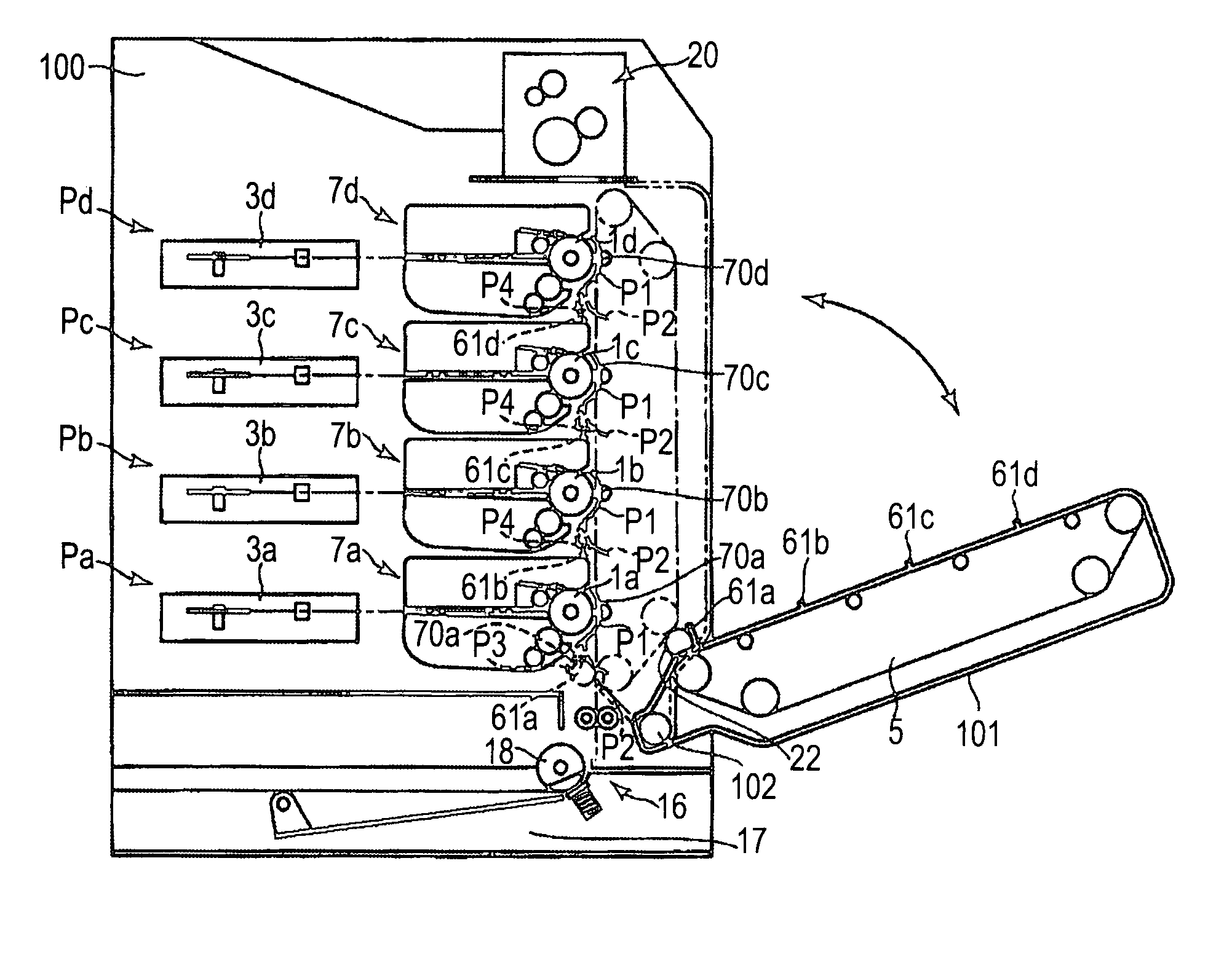
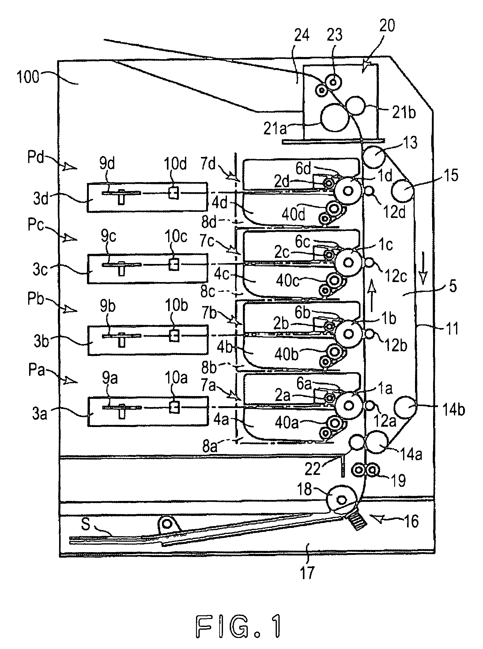
[0121]FIG. 13 is a schematic sectional view of the electrophotographic image forming apparatus in another embodiment of the present invention. The electrophotographic image forming apparatus in this embodiment is the same in structure as the electrophotographic color image forming apparatus in the first embodiment, except that the stations Pa, Pb, Pc, and Pd in this embodiment are stacked in parallel in the direction slightly angled from the true vertical direction. Thus, the components, members, portions, etc., the image forming apparatus in this embodiment identical to those of the image forming apparatus in the first embodiment will be given the same referential symbols as those given for the description of the first embodiment so that the descriptions of the first embodiment can be borrowed for the description of the second embodiment.

[0122]Thus, essentially, the aspect of the electrophotographic image forming apparatus in this embodiment, which characterises the apparatus, will...

embodiment 3

[0149]Next, the electrophotographic image forming apparatus in another embodiment of the present invention will be described.

[0150]The electrophotographic image forming apparatus in this embodiment is the same as the electrophotographic color image forming apparatus in the above described second embodiment. Thus, the components, members, portions, etc., of the image forming apparatus in this embodiment identical in structure and function to those of the image forming apparatus in the second embodiment will be given the same reference symbols as those given for the description of the second embodiment, and will not be described regarding its structure, operation, etc.

[0151]Hereinafter, referring to FIGS. 16 and 17, essentially, the aspect of the shutter mechanism 120 of the electrophotographic image forming apparatus in this embodiment, which characterises this embodiment, will be described. FIG. 16 shows the unit 5 which is open, and the shutters 70 (70a, 70b, 70c, and 70d) which ar...


PUM


Abstract

A plurality of process cartridges are detachably mountable to an electrophotographic image forming apparatus along a substantially vertical line. The cartridges each have an electrophotographic photosensitive drum, process means actable on the drum, and a drum shutter movable between first and second positions. The apparatus includes mounting portions for detachably mounting the cartridges, an opening for permitting passage of the cartridges into the apparatus, a covering member for covering the opening, and a pressing member for moving the shutter to the second position thereof when the covering member moves from an open position to a closed position. An angle of rotation of the shutter rotated from the first to the second position in the bottommost cartridge is larger than an angle of rotation of the shutter rotated from the first position to the second position in another one of said process cartridges.

Description

FIELD OF THE INVENTION AND RELATED ART[0001]The present invention relates to an electrophotographic image forming apparatus in which a plurality of process cartridges having a drum shutter for protecting an electrophotographic photosensitive drum are removably mountable.[0002]Here, an electrophotographic image forming apparatus is an image forming apparatus for forming an image on a recording medium with the use of an electrophotographic image forming method. The examples of an electrophotographic image forming apparatus include an electrophotographic copying machine, an electrophotographic printer (for example, a laser printer, an LED printer, etc.), a facsimile apparatus, a word processor, and a combination of two or more of the preceding apparatuses (multifunction printer, etc.).[0003]A process cartridge is a cartridge which is removably mountable in the main assembly of an image forming apparatus, and in which a minimum of one among a charging means, a developing means, and a cl...

Claims


Application Information

Patent Timeline
Patent Type & Authority Patents(United States)
IPC IPC(8): G03G21/18G03G21/16G03G15/00G03G15/01
CPCG03G21/1832G03G2215/0119G03G2221/1609G03G2221/1884
Inventor SATO, MASAAKIMIYABE, SHIGEOKOTSUKA, HIDEKI
Owner CANON KK
Why Eureka
Try Eureka