
Method of manufacturing an automotive differential having an input pinion

a technology of input pinion and automotive differential, which is applied in the direction of gearing, couplings, hoisting equipments, etc., can solve the problems of complex and costly input pinions of automotive differential assemblies, add to the cost of differential assembly, and initial forming of input pinions

Inactive Publication Date: 2007-01-02
AMERICAN AXLE & MFG
View PDF31 Cites 41 Cited by
  • Summary
  • Abstract
  • Description
  • Claims
  • Application Information

AI Technical Summary

Benefits of technology

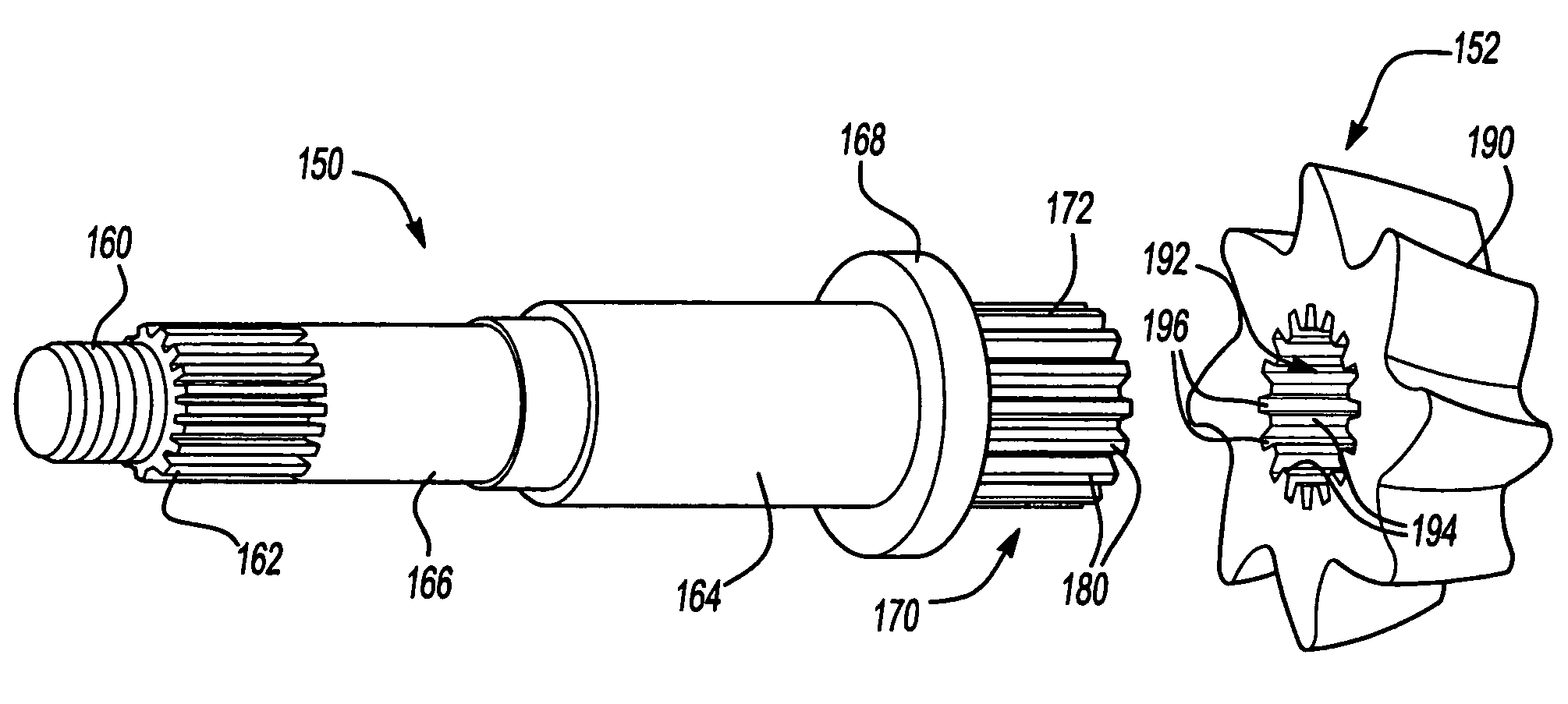
[0010]In yet another form, the present teachings provide a method for fabricating an input pinion for an automotive differential. The method includes: providing a tubular shaft; roll forming the tubular shaft to define a plurality of spline teeth and a set of threads; forging a pinion, the pinion including a plurality of teeth, each tooth being formed in the forging step to a size that is larger than a desired tooth size by an amount that is less than or equal to about 0.04 inch; performing at least...

Problems solved by technology

As is well known in the art, the fabrication of a typical input pinion for an automotive differential assembly is complex and costly and as such, greatly adds to the cost of the differential assembly.
One such drawback relates to the initial forming of the input pinion through forging.
This forging operation is relatively complex due to the shape of the input pinion and as such, the tooling for the forging operation is generally complex and expensive.
Another such drawback concerns the machining of the input pinion.
Furthermore, the protracted nature of the machining operations often results in an average cycle time that exceeds one or more days in length.
Yet another drawback concerns the material from which the input pinion is formed.
Such steels, however, generally lack the strength that is desired for an input pinion and as such, a time consuming and costly carburization process is typically employed to create a layer of relatively high carbon steel on the surface of the input pinion.

Method used


Image

  • Method of manufacturing an automotive differential having an input pinion
  • Method of manufacturing an automotive differential having an input pinion
  • Method of manufacturing an automotive differential having an input pinion

Examples


Embodiment Construction

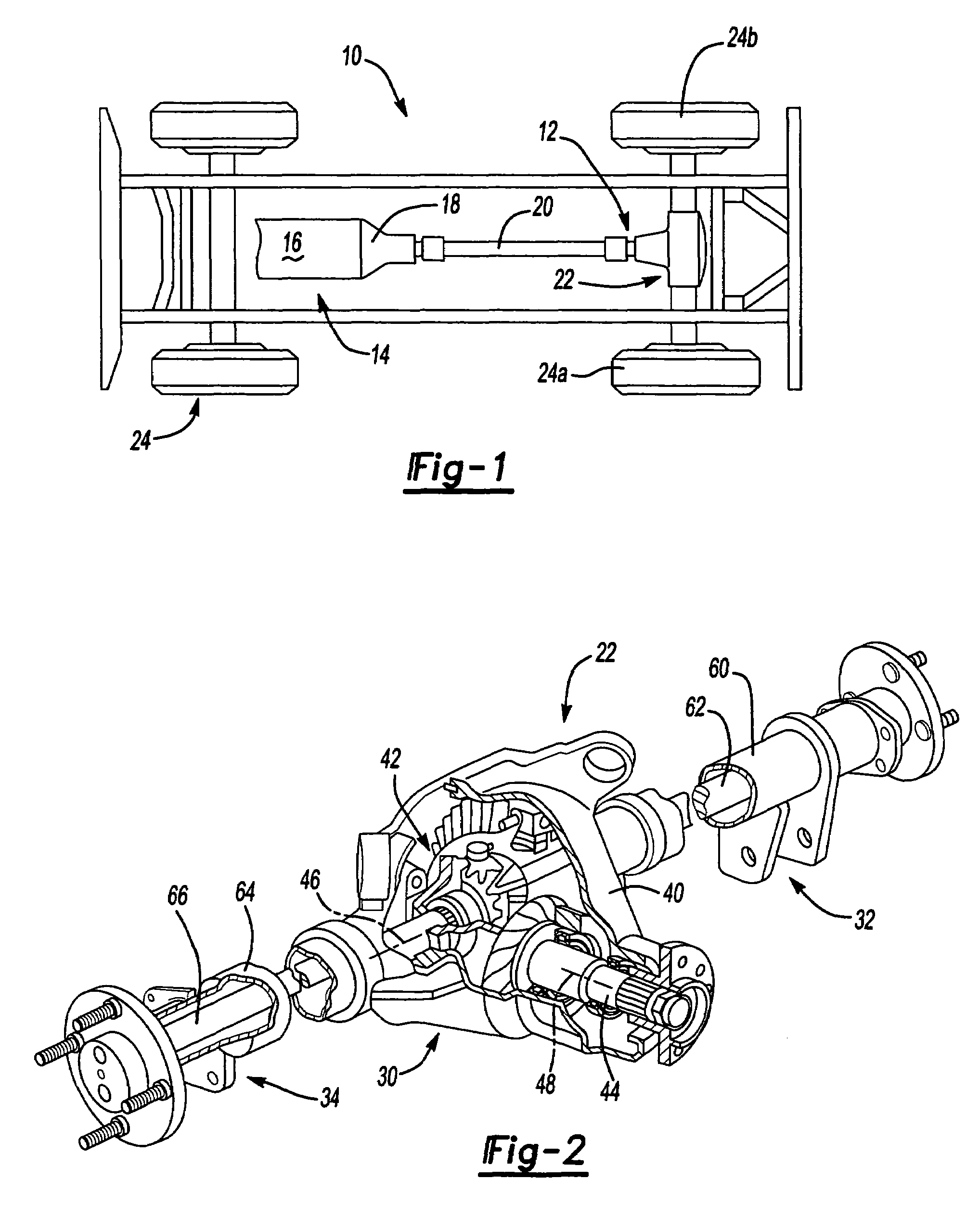
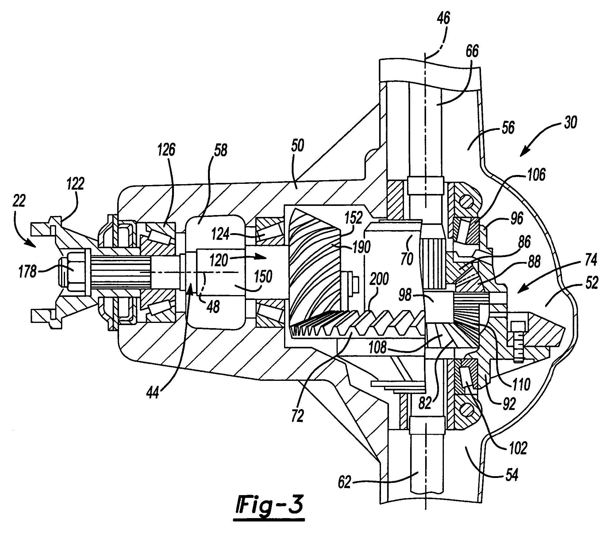
[0021]With reference to FIG. 1 of the drawings, a vehicle having a differential assembly that is constructed in accordance with the teachings of the present invention is generally indicated by reference numeral 10. The vehicle 10 may include a driveline 12 that is drivable via a connection to a power train 14. The power train 14 may include an engine 16 and a transmission 18. The driveline 12 may include a drive shaft 20, a rear axle 22 and a plurality of wheels 24. The engine 16 may be mounted in an in-line or longitudinal orientation along the axis of the vehicle 10 and its output may be selectively coupled via a conventional clutch to the input of the transmission 18 to transmit rotary power (i.e., drive torque) therebetween. The input of the transmission 18 may be commonly aligned with the output of the engine 16 for rotation about a rotary axis. The transmission 18 may also include an output and a gear reduction unit. The gear reduction unit may be operable for coupling the tra...


PUM

PropertyMeasurementUnit
Fractionaaaaaaaaaa
Fractionaaaaaaaaaa
Fractionaaaaaaaaaa

Abstract

A method for fabricating an input pinion for an automotive differential that includes: providing a shaft; forging a pinion with a plurality of teeth such that each tooth is formed to at least a near-net size, forming a hole in the pinion, pressing an end of the shaft into the hole in the pinion, and securing the shaft to the pinion.

Description

CROSS-REFERENCE TO RELATED APPLICATIONS[0001]This is a continuation-in-part of U.S. patent application Ser. No. 09 / 930,611 filed Aug. 15, 2001, now abandoned.FIELD OF THE INVENTION[0002]The present invention generally relates method for manufacturing an input pinion that is adapted for use in vehicle differentials.BACKGROUND OF THE INVENTION[0003]As is well known in the art, the fabrication of a typical input pinion for an automotive differential assembly is complex and costly and as such, greatly adds to the cost of the differential assembly. A typical process for forming an input pinion includes forging of the gear and shaft, annealing, straightening, rough machining, carburizing, hardening and finish machining operations. Additionally, the input pinion may be processed through a lapping operation wherein the teeth of the input pinion are lapped with the teeth of the ring gear to match the input pinion and ring gear to one another. The lapping operation matches the input pinion an...

Claims


Application Information

Patent Timeline
IPC IPC(8): B21D53/28B21K1/30F16H48/08F16D1/06F16D1/068F16H48/06F16H55/17F16H57/00
CPCF16D1/06F16D1/068F16D1/10F16H57/0025F16H55/17F16D2001/103F16H48/08F16H48/42Y10T29/49464Y10T29/49467Y10T29/49462Y10T29/49465Y10T29/4948
Inventor PRUCHER, BRYAN P.
Owner AMERICAN AXLE & MFG
Learn More