Apparatus for producing slush nitrogen and method for producing the same

a technology of slush nitrogen and apparatus, which is applied in the field of apparatus for producing slush nitrogen and method for producing the same, can solve the problems of the method for producing economically slush nitrogen comprising solid nitrogen having a homogenous and fine particle size is not established, and the uneven and large solid hydrogen particles are also uneven and large. , to achieve the effect of good heat conductive characteristics, widening the selection range of super conductive materials,

Inactive Publication Date: 2007-01-02
MAYEKAWA MFG CO LTD
View PDF18 Cites 6 Cited by
  • Summary
  • Abstract
  • Description
  • Claims
  • Application Information

AI Technical Summary

Benefits of technology

[0019]According to the present invention, a particle size of the solid nitrogen is controlled by varying a pressure for supplying the cooling agent to the ejector. When the pressure is made higher, a speed blowing from a nozzle of the ejector becomes greater so that particles of liquid nitrogen sucked become finer to produce solid nitrogen having a finer particle size. Further, variation of a diameter of the hole of a nozzle and its combination with the speed can control a wide range of particle size.
[0065]Further, since a latent heat of melting of solid nitrogen is utilized using slush nitrogen, there is a cooling effect 12.5 times as much as the case of sensible heat of liquid nitrogen per unit mass of a cooling agent. Therefore, less cooling agent than in case of cooling with liquid nitrogen is necessary so that an apparatus can be made smaller.

Problems solved by technology

However, a method for producing economically slush nitrogen comprising solid nitrogen having a homogenous and fine particle size is not established.
Though, in the above methods, slush nitrogen is obtained using liquid nitrogen instead of liquid hydrogen, each has the following problem.
In the freezing-melting method (2), air might intrude into the vessel from the outside because of depressurization of the inside of the low temperature vessel and besides; there is a drawback that particles of solid hydrogen are uneven and large.
In the helium freezing method (3), particles of solid hydrogen are also uneven and large, and a particular heat exchanger is necessary.
As a melting point of solid nitrogen is 63.17 K, which is far higher than that of solid hydrogen, if this method is applied for a production of solid nitrogen, the nozzle is occluded unless a diameter of the nozzle hole and a flow volume are large, resulting in that fine particles of solid nitrogen can not stably obtained.
Even if the art is applied to production of slush nitrogen, an apparatus for liquefaction is necessary and a temperature has to be lower than that of nitrogen or hydrogen liquefaction when using helium that is already used as a cooling agent by recondensation thereof, whereby an apparatus becomes large and also production cost becomes high.
There has been no appropriate method for evaluating solid nitrogen concentration in slush nitrogen.
In addition, insulating device needs to be added for it is used under very low temperature, which results in high production cost.
Furthermore, because nitrogen comes to be mixed in the apparatus for liquefying helium, long operation of the apparatus is difficult or an apparatus with a high performance is needed.
However, a temperature that cools liquid nitrogen of a melting point of 63 K without solidifying is limited to 65 K at best.
More specifically, as a temperature range capable of cooling with liquid nitrogen as a liquid state utilizing a sensible heat thereof is narrow and a heat capacity is small, a vast amount of liquid nitrogen is necessary for cooling (eliminating heat) so that a super conductive apparatus becomes large in size.
If a cooling temperature rises to about a boiling point with this method, the performance of a super conductive device is limited to that temperature.

Method used


Image

  • Apparatus for producing slush nitrogen and method for producing the same
  • Apparatus for producing slush nitrogen and method for producing the same
  • Apparatus for producing slush nitrogen and method for producing the same

Examples


first embodiment

A First Embodiment

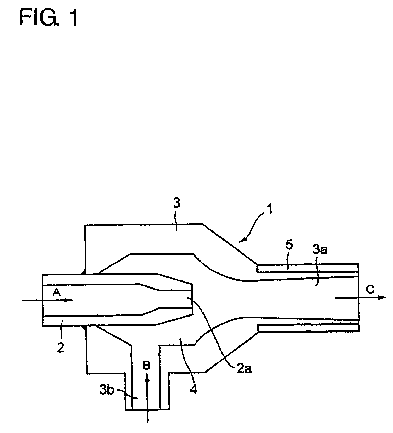
[0074]FIG. 1 is a sectional view of an ejector disposed in a low temperature vessel. As shown in FIG. 1, an ejector 1 comprises a nozzle 2 and an outer cylinder 3 having a diffuser part 3a. The nozzle 2 is protruded into the inner space 4 of the outer cylinder 3. A cooling agent of liquid or gas is supplied as shown as an arrow A and blown out of a nozzle end 2a toward the diffuser part 3a. Liquid nitrogen filled in a low temperature vessel is sucked into the inner space 4 from a suction hole 3b of the outer cylinder 3 as shown as an arrow B and blown into an inner space of the low temperature vessel together with a cooling agent flow through the diffuser part 3a. A heater 5 is provided at the outside of the diffuser part 3a in order to prevent for solid nitrogen to be frozen and fixed thereto.

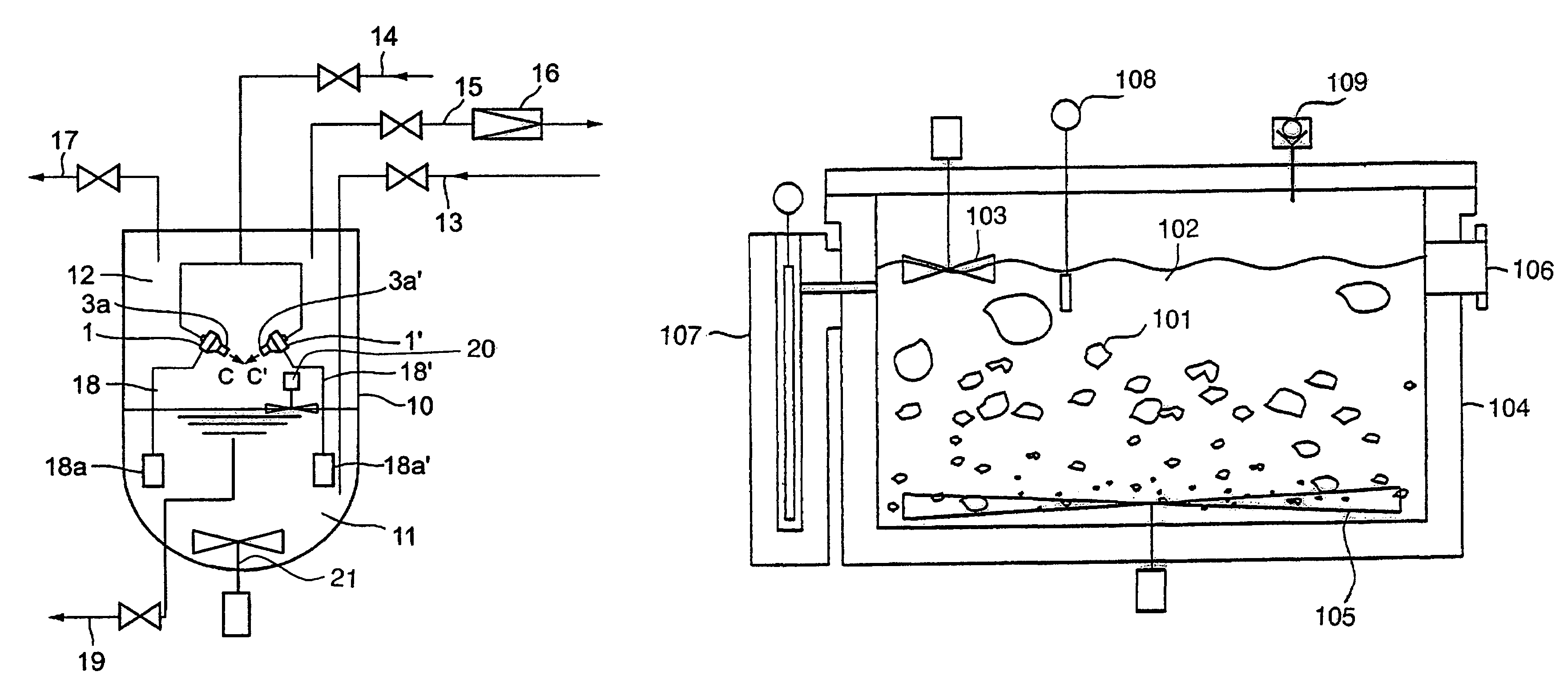
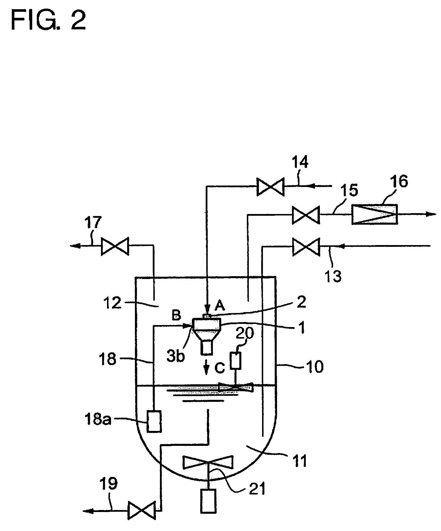
[0075]FIG. 2 is a drawing showing a piping of a low temperature vessel provided with an ejector. FIG. 3 is a drawing showing a case in which two ejectors are disposed face to...

second embodiment

A Second Embodiment

[0085]FIG. 5 is a schematic illustration of an apparatus of a second embodiment according to the present invention. In FIG. 5, 104 is an adiabatic vessel; 102 is liquid nitrogen held in the vessel; 109 is a vacuum pump for depressurizing a gaseous part (a means for depressurizing); 108 is a thermometer detectable of the triple point (a means for detecting temperature); 107 is a level gauge capable of finding a present value of the volume; 103 is a stirring blade for surface part capable of breaking a plate of solid nitrogen solidified on the surface (a means for stirring a part of liquid surface); 105 is a stirring blade for bottom part capable of further pulverizing sedimented solid nitrogen (a means for stirring a bottom part).

[0086]Liquid nitrogen 102 is stored in the adiabatic vessel 104 and a gaseous phase of the inner part of the vessel is depressurized with a vacuum pump 109. When depressurization proceeds, liquid nitrogen is evaporated and a temperature of...

third embodiment

A Third Embodiment

[0089]Next, an embodiment of evaluating slush nitrogen concentration is described. Let a latent heat of vaporization of nitrogen, a latent heat of solidification, a density of liquid nitrogen, a density of solid nitrogen, a volume of nitrogen at triple point, a volume of nitrogen after production of slush nitrogen, a liquid nitrogen corresponding value of a volume of vaporized nitrogen, a volume of vaporized solid nitrogen, a heat intruded into the adiabatic vessel, and a time consumed for production of slush nitrogen be Hv (kJ / kg), Hs (kJ / kg), M1 (kg / m3), Ms (kg / m3), Vs (m3), Vf (m3), Xv (m3), Xs (m3), Q (kW), and T (s) respectively,[0090]from energy conservation law,

Hv×M1×Xv=Hs×Ms×Xs+Q×T  (1)[0091]from law of conservation of mass,

Vs×M1=(Vf−Xs)×M1+Xs×Ms+Xv×M1  (2).

[0092]Xv and Xs are found from the above simultaneous equations and the obtained values are substituted into the following equation to find a slush nitrogen concentration (IPF).

IPF=Xs×Ms / ((Vf−Xs)×M1+Xs×M...


PUM

PropertyMeasurementUnit
temperatureaaaaaaaaaa
melting pointaaaaaaaaaa

Abstract

Liquid nitrogen is filled in a low temperature vessel; an ejector that sucks liquid nitrogen by blowing a cooling agent (liquid or gas) such as low temperature helium gas or liquid helium of pressure higher than in the space within the vessel is disposed in the vessel; the liquid nitrogen blown with the cooling agent is cooled by the cooling agent to become fine particles of solid nitrogen which fall down; and gas in a space of the vessel is discharged out of the vessel so as to maintain the pressure of the space higher than the atmospheric pressure.A gaseous phase of liquid nitrogen in an adiabatic vessel is depressurized to vaporize nitrogen in a liquid phase so that a temperature of the nitrogen is reached to the triple point of nitrogen by lowering temperature thereby and solid nitrogen is produced by keeping at the triple point, and that the produced solid nitrogen is transformed into slush by stirring the content of the adiabatic vessel.In a method for cooling a super conductive body in which a material showing a state of super conductance in the vicinity of the temperature of liquid nitrogen or of the temperature liquid nitrogen and solid nitrogen coexist is used, a method for cooling a super conductive body characterized in that the super conductive body is immersed in slush nitrogen held in an adiabatic vessel, and that the body is contacted with slush nitrogen to cool.

Description

[0001]This application is a continuation of International Application PCT / JP2004 / 000809, with an international filing date of Jan. 29, 2004.FIELD OF THE INVENTION[0002]The present invention is related to a method and an apparatus for producing slurry of a mixture of liquid nitrogen and solid nitrogen, that is slush nitrogen, and a simple method for evaluating solid concentration of the same and a method for cooling using the same.DESCRIPTION OF THE RELATED ART[0003]Liquid nitrogen is widely used as a cooling agent. When a sherbet-like mixture of solid nitrogen and liquid nitrogen is used, its density and cooling capacity per unit mass are increased so that the mixture becomes an efficient cooling agent. However, a method for producing economically slush nitrogen comprising solid nitrogen having a homogenous and fine particle size is not established.[0004]Slush nitrogen has an excellent capacity of absorbing heat load compared with liquid nitrogen because a latent heat of melting of ...

Claims


Application Information

Patent Timeline
Patent Type & Authority Patents(United States)
IPC IPC(8): F25J1/00F17C5/00C01B21/00F25C1/00F25D3/10F25J1/02H04N5/00H04N7/167H04N7/24
CPCF25C1/00F25J1/0015F25J1/0221F25J1/0251F25J1/0276F25D3/10F25J2205/90F25J2205/30F25J2210/42F25J2240/60F25J2205/20
Inventor KAWAMURA, KUNIAKIMACHIDA, AKITOIKEUCHI, MASAMITSUHATTORI, KAZUHIROMATSUO, KOUICHIYANAGI, HIDEHARU
Owner MAYEKAWA MFG CO LTD
Why Eureka
Try Eureka