Pivotable pylon for external carriage of aircraft stores

a pylon and aircraft technology, applied in the direction of launch weapons, fuselages, transportation and packaging, etc., can solve the problems of limiting the space available for the external carriage of stores, and the common pylon configuration used at all front-to-back stations on each side of the aircraft does not produce the optimal weapons loadou

Active Publication Date: 2007-01-02
THE BOEING CO
View PDF3 Cites 28 Cited by
  • Summary
  • Abstract
  • Description
  • Claims
  • Application Information

AI Technical Summary

Benefits of technology

[0005]In accordance with one or more embodiments of the present invention, a universal, pivotable pylon is provided for the external carriage of aircraft stores, which is usable at any station on either side of the aircraft, and which is compatible with a wide variety of internal and external stores and the associated clearance constraints unique to each pylon station of the aircraft. The pylon enables the aircraft to carry an optimum number of stores externally of the aircraft.
[0008]A locking mechanism, such as locking pins, is provided for locking the pivoting structure in a selected one of a plurality of angular pivot positions relative to the strongback, thereby enabling the angular position of the stores items to adjusted relative to the exterior surface of the aircraft, and thereby provide the necessary clearance between the stores and adjacent aircraft structures, such as the doors of a weapons bay, for each unique pylon mounting station thereon. In a high-performance aircraft, an aerodynamic fairing that extends generally between the external surface of the aircraft and an external surface of the at least one stores item may be disposed on the pylon to limit its parasitic drag.

Problems solved by technology

In modern, high-performance military aircraft, e.g., those with smoothly changing shapes, such as the so-called “Blended-Wing-Body” (“BWB”) family of aircraft, the space on the underside of the aircraft's fuselage between its equipment bays and its engine nacelles is relatively narrow, thereby limiting the space available for the external carriage of stores.
However, a common pylon configuration used at all front-to-rear stations on each side of the aircraft does not produce an optimal weapons loadout due to the variety of clearance constraints imposed between the loaded pylons and the doors of the equipment bays and / or the engine nacelles.

Method used


Image

  • Pivotable pylon for external carriage of aircraft stores
  • Pivotable pylon for external carriage of aircraft stores
  • Pivotable pylon for external carriage of aircraft stores

Examples


Embodiment Construction

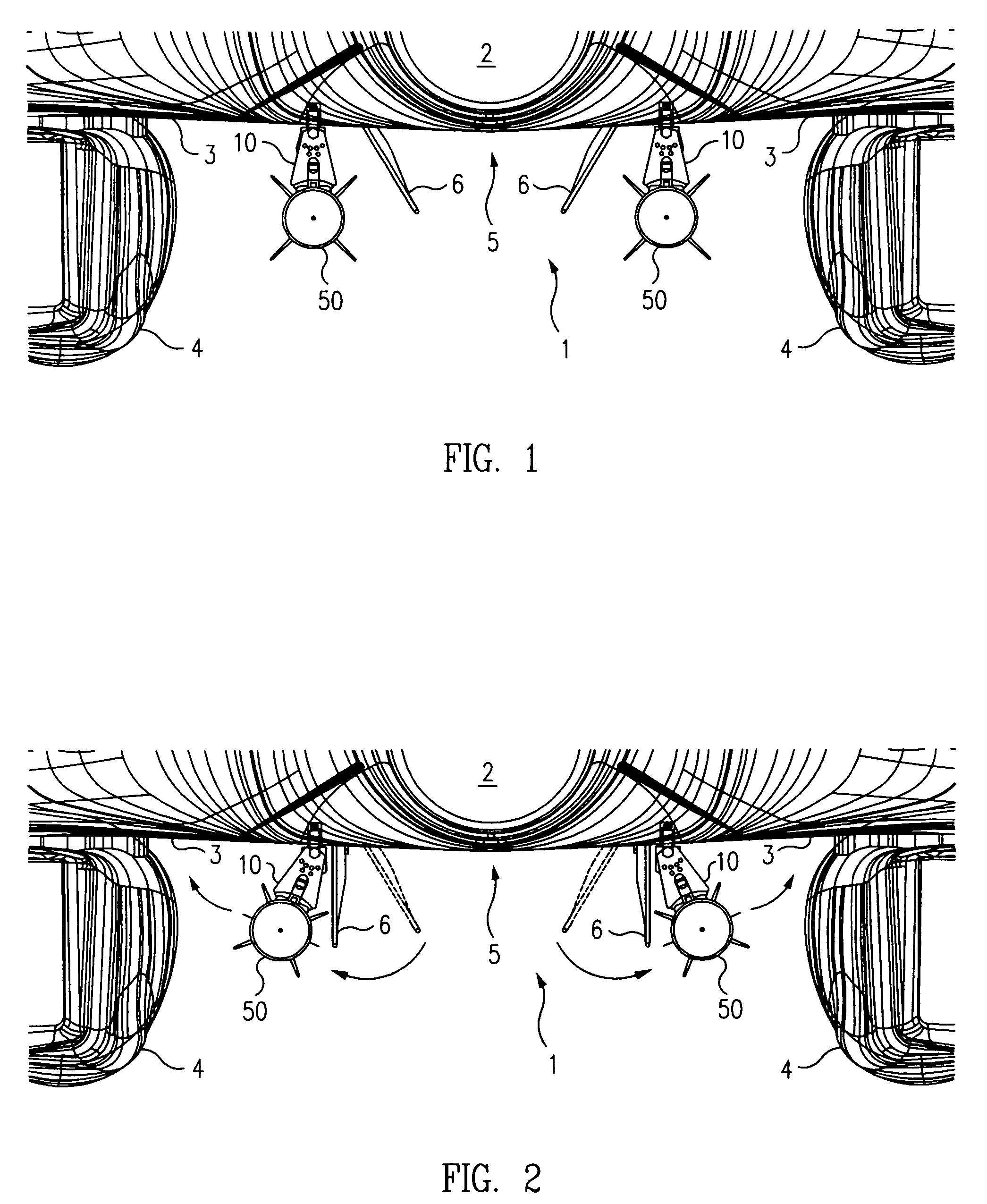
[0017]A partial front elevation view of a high-performance military aircraft 1, e.g., a Boeing B-1B bomber, incorporating a pair of pivotable pylons 10 in accordance with an exemplary embodiment of the present invention is illustrated in FIG. 1. The aircraft comprises an elongated fuselage 2 and a pair of wings 3, each having one or more engine nacelles 4 depending therefrom generally outboard of the fuselage. The wings have extended roots that blend smoothly into the fuselage, giving rise to the descriptive term, “blended-wing-body” (“BWB”) design. Such aircraft are typically provided with one or more longitudinally distributed equipment or weapons bays 5, each having a pair of bay doors 6 that swing open from a fully closed position flush with the fuselage (not illustrated), to a half opened position, as illustrated in FIG. 1, for the discharge of certain types of ordinance not requiring fully opened bay doors, e.g., 2000 lb. bombs, to a fully opened position (see FIG. 2), for the...


PUM


Abstract

A pivotable pylon for carrying stores, such as ordinance, sensors and pods external to an aircraft includes an elongated strongback coupled against an external surface of the aircraft and generally parallel to the longitudinal axis thereof. An elongated pivoting structure is pivotally coupled to the strongback for parallel pivotal movement relative thereto. A locking mechanism locks the pivoting structure in a selected one of a plurality of angular positions relative to the strongback. At least one stores rack is coupled to the pivoting structure for receiving and coupling at least one stores item to the pivoting structure. An aerodynamic fairing may be disposed on the pylon to decrease drag. The pylon can be mounted on either side of the aircraft and in any one of a plurality of longitudinal stations, and enables the aircraft to carry stores that are too large for its equipment bays, and to carry an optimal load of stores.

Description

TECHNICAL FIELD[0001]This invention generally relates to apparatus for carrying stores, such as weapons, fuel, sensors and the like, on an external surface of an aircraft. More particularly, this invention relates to a pivotable pylon that enables the aircraft to carry stores that are too large for its equipment bays, and to carry an optimum number of external stores.BACKGROUND[0002]The carriage of stores, such as ordinance, fuel, sensor and camera pods and the like, on an external surface of an aircraft is well known in the aviation industry, and is typically effected through the use of surface-mounted, cantilevered “pylons” that couple to the aircraft's structure, and to which the stores are then attached, either fixedly or releasably. The use of streamlined fairings extending between the skin of the aircraft and the stores to reduce parasitic drag of the pylon during flight is also known.[0003]In modern, high-performance military aircraft, e.g., those with smoothly changing shape...

Claims


Application Information

Patent Timeline
Patent Type & Authority Patents(United States)
IPC IPC(8): B64D1/12
CPCB64D1/04
Inventor LAM, TRISTIN T.ENG, EDWARD J.
Owner THE BOEING CO
Why Eureka
Try Eureka