
Injection molding unit with a device for mixing and metering plastic melt and additives

a technology of injection molding machine and injection molding unit, which is applied in the direction of manufacturing tools, food shaping, sweetmeats, etc., to achieve the effect of reducing the cross section

Inactive Publication Date: 2005-11-29
SUMITOMO SHI DEMAG PLASTICS MACHINERY
View PDF9 Cites 0 Cited by
  • Summary
  • Abstract
  • Description
  • Claims
  • Application Information

AI Technical Summary

Benefits of technology

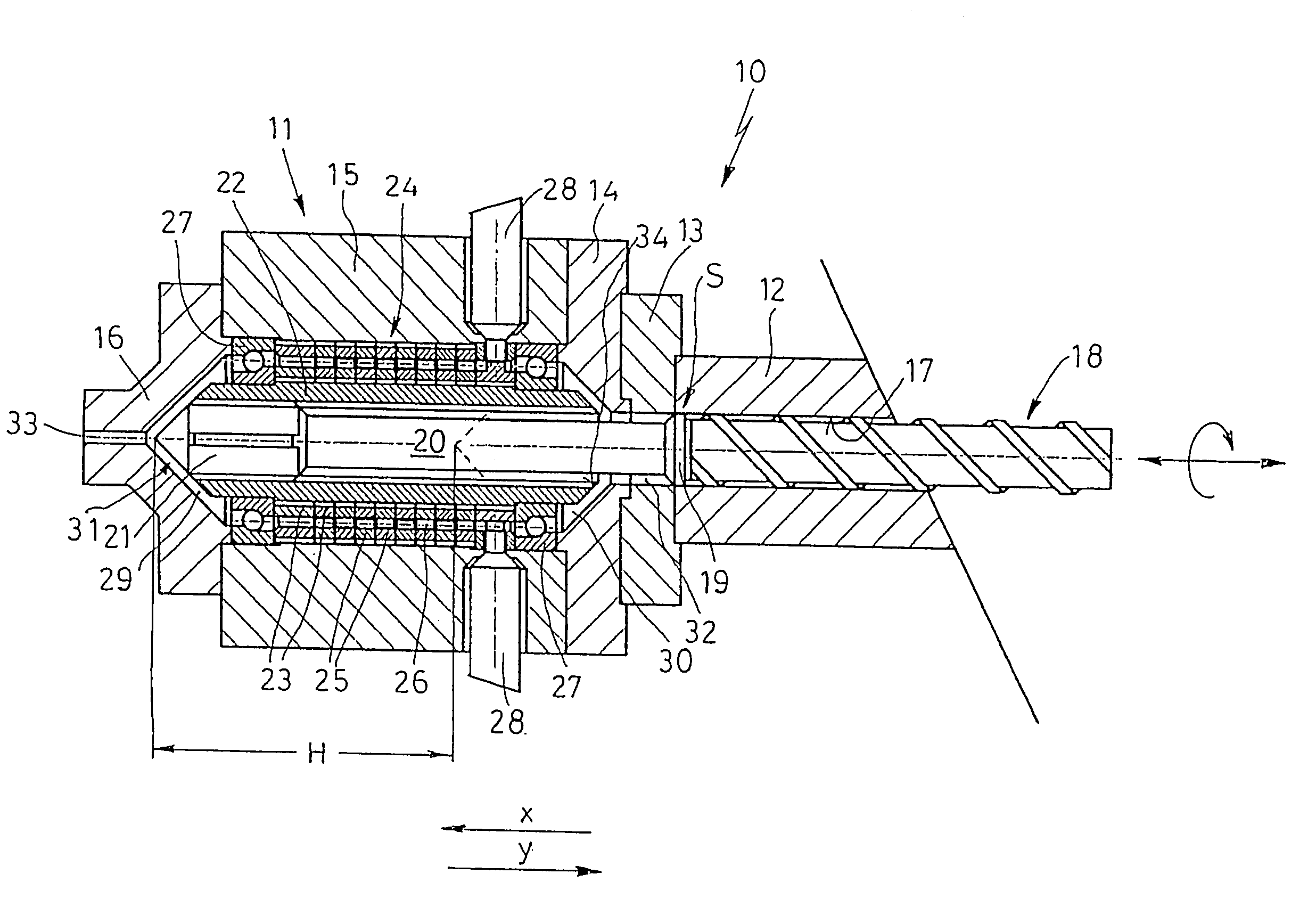
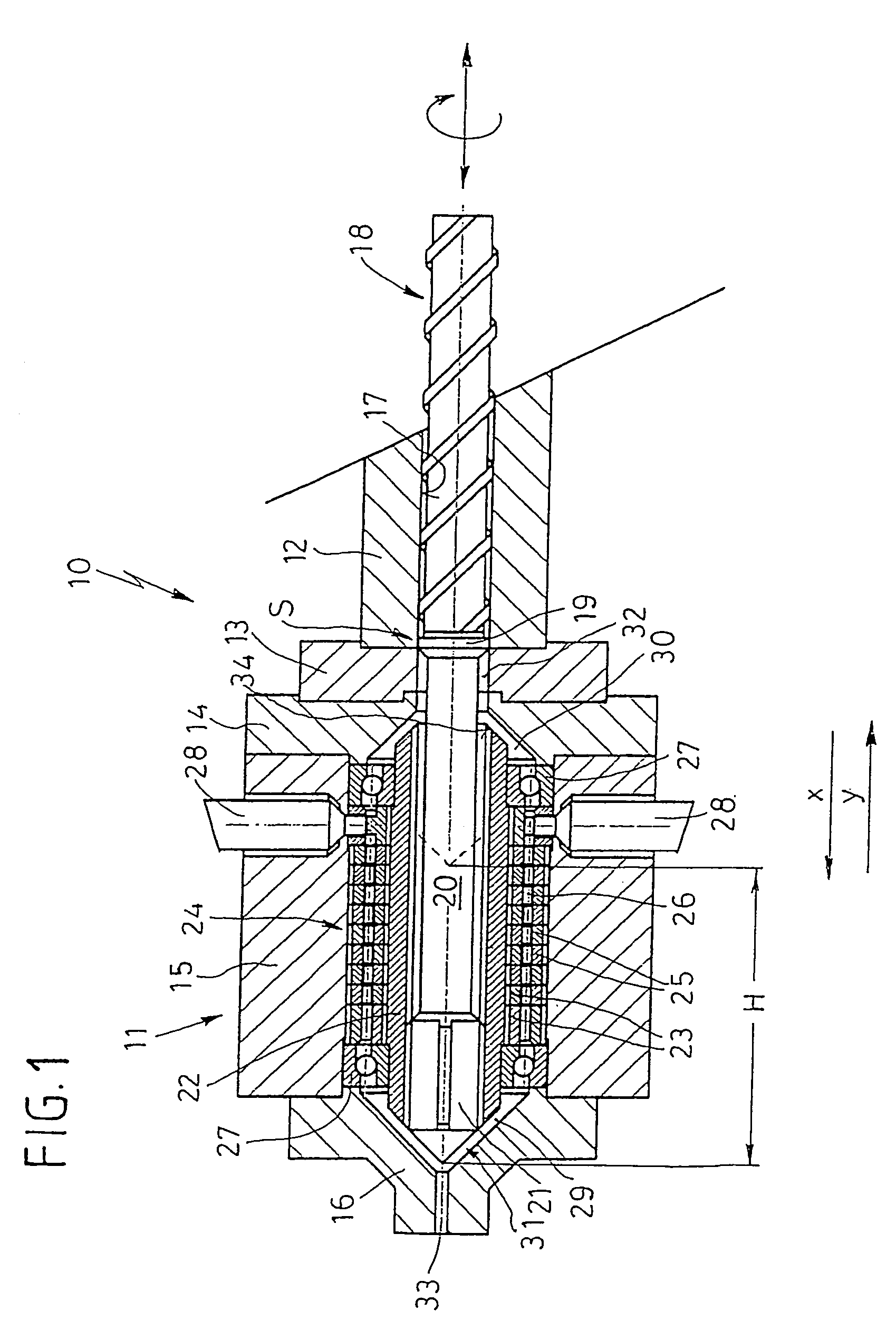
[0008]An injection device according to the invention has numerous advantages compared to prior art devices. On the one hand, no moving parts have to be sealed from outside against escape of melt, so that the construction is simplified. In addition, the coaxial configuration of the mixing and metering device results in a straight force flux while the structural size is reduced at the same time.
[0009]The mixing and metering device can advantageously embrace the plunger at least partially in a circular ring shaped manner, wherein it is basically possible in this context to motionally connect the mixing and metering device in relation to its rotation movement with the injection device. In this way, there is no need for an additional drive for the mixing and metering device so that overall the injection device becomes simpler.
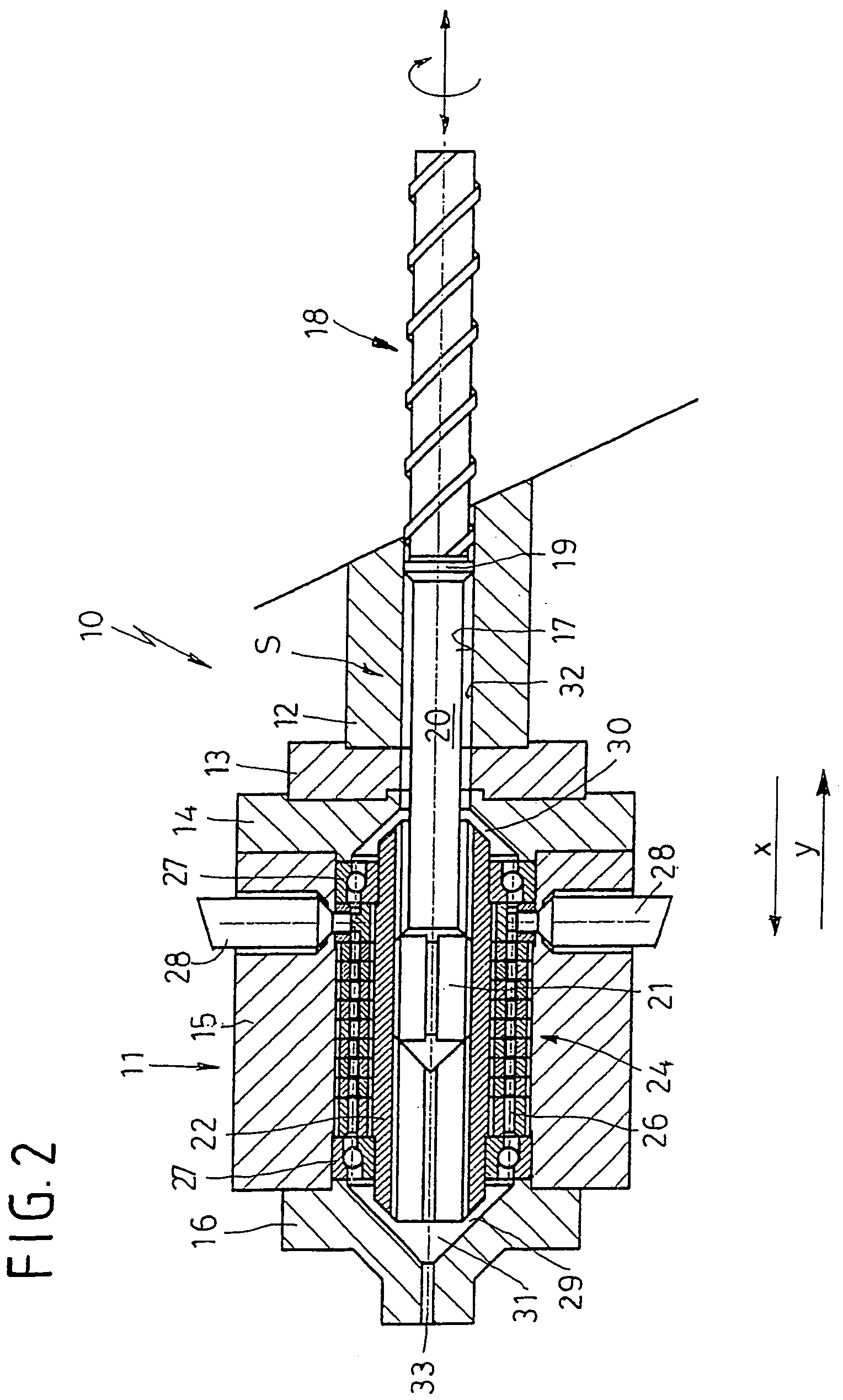
[0012]According to another advantageous feature of the present invention, the spacer element may be formed by a continuously tapered shaft, whereby the circular ring shaped flow cross section, which surrounds the shaft, is fully available for transport of the melt from the screw to the mixing and metering device. In a most simple manner, the necessary movement clearance between plunger and screw can be realized, without interrupting the flow channel for the melt, regardless of the position of the injection device.
[0013]According to still another advantageous feature of the invention, an additional intermediate component can be disposed anteriorly of the movement space of the plunger between the nozzle and a respective housing portion to provide an expanded accumulation chamber for the melt in x-direction, wherein the plunger is provided on the nozzle side with a tapered shaft which provides the expulsion of the melt. Also this embodiment has the advantage, that the “first in-first out” principle is maintained because the melt components that enter first the accumulation chamber are ultimately injected first through the nozzle into the injection mold.
[0014]It would also be conceivable in accordance with a further feature of the present invention to implement a spacer element in the form of a tapered shaft which is surrounded by a circular ring shaped flow channel defined between the shaft and the housing and having a cross section which narrows slightly conically from the screw to the plunger, and further providing an aperture ring disposed in the housing at slight distance to the plunger for reducing a cross section of the circular ring shaped flow channel, wherein the shaft has a plunger-proximal end formed with a ring-shaped constriction and is provided with at least one axial throughbore to connect a flow channel, which extends out from the screw, with the constriction of the shaft, for establishing a fluidic communication between the throughbore and the circular ring shaped flow channel. This particular feature has the advantage that no flow dead spaces are generated in the flow cross section available for the melt, even when the plunger / screw arrangement (injection device) has moved forward, so that the so-called “first in-first out” principle is maintained also here.

Problems solved by technology

These systems suffer, however, major problems as far as a permanent sealing of the shaft and plunger passageways are concerned because jointed areas that move relative to one another must be sealed to prevent against escape of plastic melt.

Method used


Image

  • Injection molding unit with a device for mixing and metering plastic melt and additives
  • Injection molding unit with a device for mixing and metering plastic melt and additives
  • Injection molding unit with a device for mixing and metering plastic melt and additives

Examples


first embodiment

[0027]Turning now to the drawing, and in particular to FIG. 1, there is shown a longitudinal section of an injection unit according to the present invention, generally designated by reference numeral 10 and forming part of an injection molding machine. The injection unit 10 includes a housing 11 which is comprised of the housing portions 12, 13, 14, 15, and 16. Disposed in the housing portions 12 and 13 is a circular cylindrical guide channel 17 in which a screw 18 of an injection device S is arranged rotatably and axially moveably. The screw 18 is provided on its free end with a thrust device in a manner not shown. Disposed on the other end of the screw 18 is a backflow prevention assembly 19 followed by a tapered shaft 20 as well as a plunger 21. The plunger 21 is arranged for longitudinal movement in a concomitantly rotating tube 22 having an outer circumferential surface for arrangement of circular ring shaped mixing elements 23 of a mixing and metering device 24. Further mixing...

third embodiment

[0034]Referring now to FIGS. 7 to 9, there are illustrated an injection unit according to the present invention, generally designated by reference numeral 10″. Parts corresponding with those in FIG. 1 are denoted by identical reference numerals and not explained again. The description below will again center primarily on the differences between the embodiments. In this embodiment, provision is made for the arrangement of an intermediate component 40 which is arranged between the housing portion 16 and the housing portion 15, for realizing a substantial prolongation of the accumulation chamber 31 in x-direction.

[0035]Furthermore, the plunger 21 is provided with a shaft-like ejection element 41 which has a smaller diameter than the plunger 21 so that a ring space 42 is left as flow cross section for the melt. After expulsion of the melt from the accumulation chamber 31 (see FIG. 7), the injection device S is caused to move again, just like in the other embodiments, to start a rotary m...


PUM

PropertyMeasurementUnit
lengthaaaaaaaaaa
inner diameteraaaaaaaaaa
distanceaaaaaaaaaa

Abstract

An injection unit for an injection molding machine includes an injection device in the form of a plunger / screw, which is driven axially and rotationally in a housing, and a device intended for mixing and metering plastic melt and including an inlet for introduction of an additive. A spacer element is disposed between a backflow prevention assembly of the screw and the plunger, with the spacer element having a length, which corresponds at least to the stroke of the injection device. The spacer element has a first flow channel for establishing in each position a fluidic connection with a second flow channel which initially extends radially in an outward direction and then parallel to the movement and guide area of the plunger to an area between a nozzle and the plunger. The second flow channel extends through the mixing and metering device arranged adjacent to a movement and guide area of the plunger.

Description

CROSS-REFERENCES TO RELATED APPLICATIONS[0001]This application is a continuation of prior filed copending PCT International application no. PCT / DE02 / 02623, filed Jul. 18, 2002, which designated the United States and on which priority is claimed under 35 U.S.C. §120, the disclosure of which is hereby incorporated by reference.[0002]This application claims the priority of German Patent Application, Serial No. 101 37 073.3, filed Jul. 28, 2001, pursuant to 35 U.S.C. 119(a)–(d), the disclosure of which is incorporated herein by reference.BACKGROUND OF THE INVENTION[0003]The present invention relates, in general, to an injection unit of an injection molding machine, and more particularly to an injection device for use in such an injection unit.[0004]An injection unit of a type involved here typically includes an injection device which is configured as plunger / screw and operated in a housing for axial as well as rotating movements and which is provided with a backflow prevention assembly....

Claims


Application Information

Patent Timeline
Patent Type & Authority Patents(United States)
IPC IPC(8): B29C44/34B29C45/18B29C45/50B29C45/58
CPCB29C45/1816B29C45/581B29C44/3442
Inventor SCHURMANN, ERICH
Owner SUMITOMO SHI DEMAG PLASTICS MACHINERY
Learn More