

Method for controlling the tilt position of a marine propulsion device
- Summary
- Abstract
- Description
- Claims
- Application Information
AI Technical Summary
Benefits of technology
Problems solved by technology
Method used
Image

Examples
Embodiment Construction
[0025]Throughout the description of the preferred embodiment of the present invention, like components will be identified by like reference numerals.
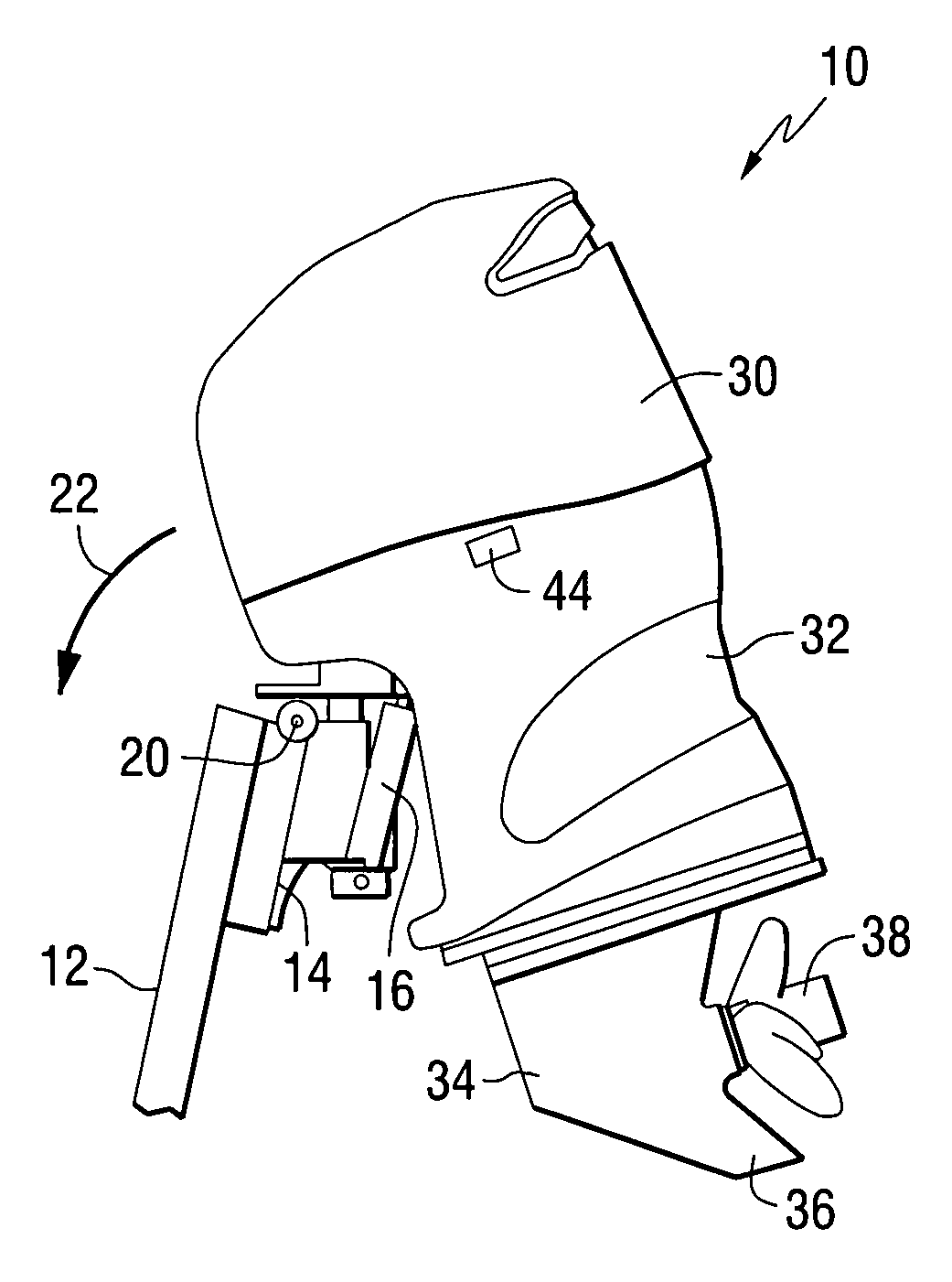
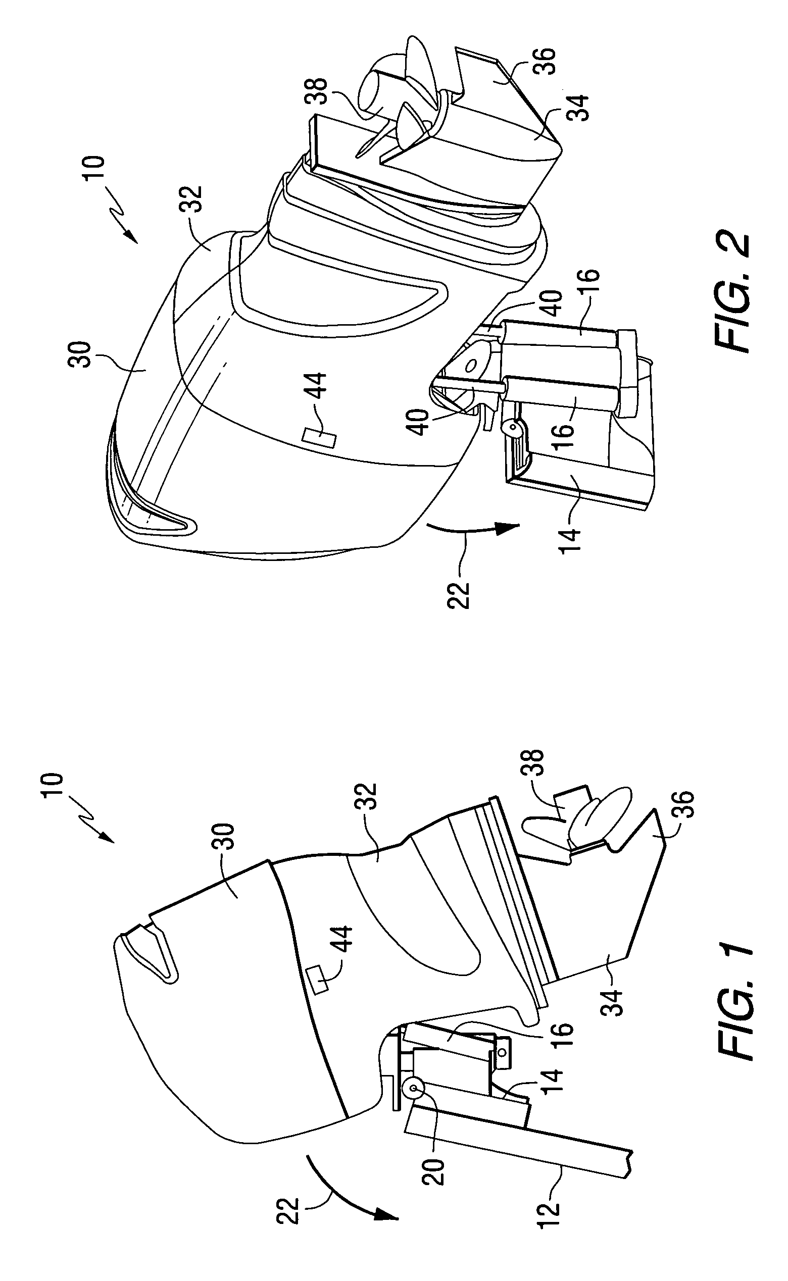
[0026]FIG. 1 is a side view of a marine propulsion device 10, such as an outboard motor, which is attached to a transom 12 of a marine vessel. A transom bracket 14 facilitates the attachment of the support mechanism for the outboard motor to the transom 12. A hydraulic cylinder 16 is configured to exert a force on the outboard motor to cause it to rotate about a tilt axis 20. When the outboard motor is tilted upwardly, it moves about the tilt axis 20 in the direction represented by arrow 22.
[0027]With continued reference to FIG. 1, the outboard motor 10 typically comprises a cowl structure 30, a driveshaft housing 32, a lower unit comprising a gear case 34 and skeg 36, and a propeller 38 attached to a propeller shaft (not visible in FIG. 1) that is supported within the gear case 34 for rotation about a generally horizontal axis when the...
PUM
 Abstract
Description
Claims
Application Information