Method and apparatus for sensing voltage in an automatic transfer switch system

a technology of automatic transfer switch and voltage sensing circuit, which is applied in the direction of relays, emergency power supply arrangements, transportation and packaging, etc., can solve the problems of large, heavy, and relatively expensive transformers provided in these systems, and significantly to the overall size and cost of the system, and the ats system which uses these types of voltage sensing circuits, in general, is large and expensiv

Active Publication Date: 2007-01-02
KOHLER POWER SYST
View PDF15 Cites 21 Cited by
  • Summary
  • Abstract
  • Description
  • Claims
  • Application Information

AI Technical Summary

Problems solved by technology

While prior art voltage sensing circuits are generally successful in providing an accurate sensing signal, to provide a linear transfer characteristic and prevent saturation of the core at these relatively low frequencies of operation, the transformers provided in these systems are typically large, heavy, and relatively expensive.
The transformers therefore contribute significantly to the overall size and cost of the system.
ATS systems which use these types of voltage sensing circuits, therefore, are also typically large and expensive.

Method used


Image

  • Method and apparatus for sensing voltage in an automatic transfer switch system
  • Method and apparatus for sensing voltage in an automatic transfer switch system
  • Method and apparatus for sensing voltage in an automatic transfer switch system

Examples


Embodiment Construction

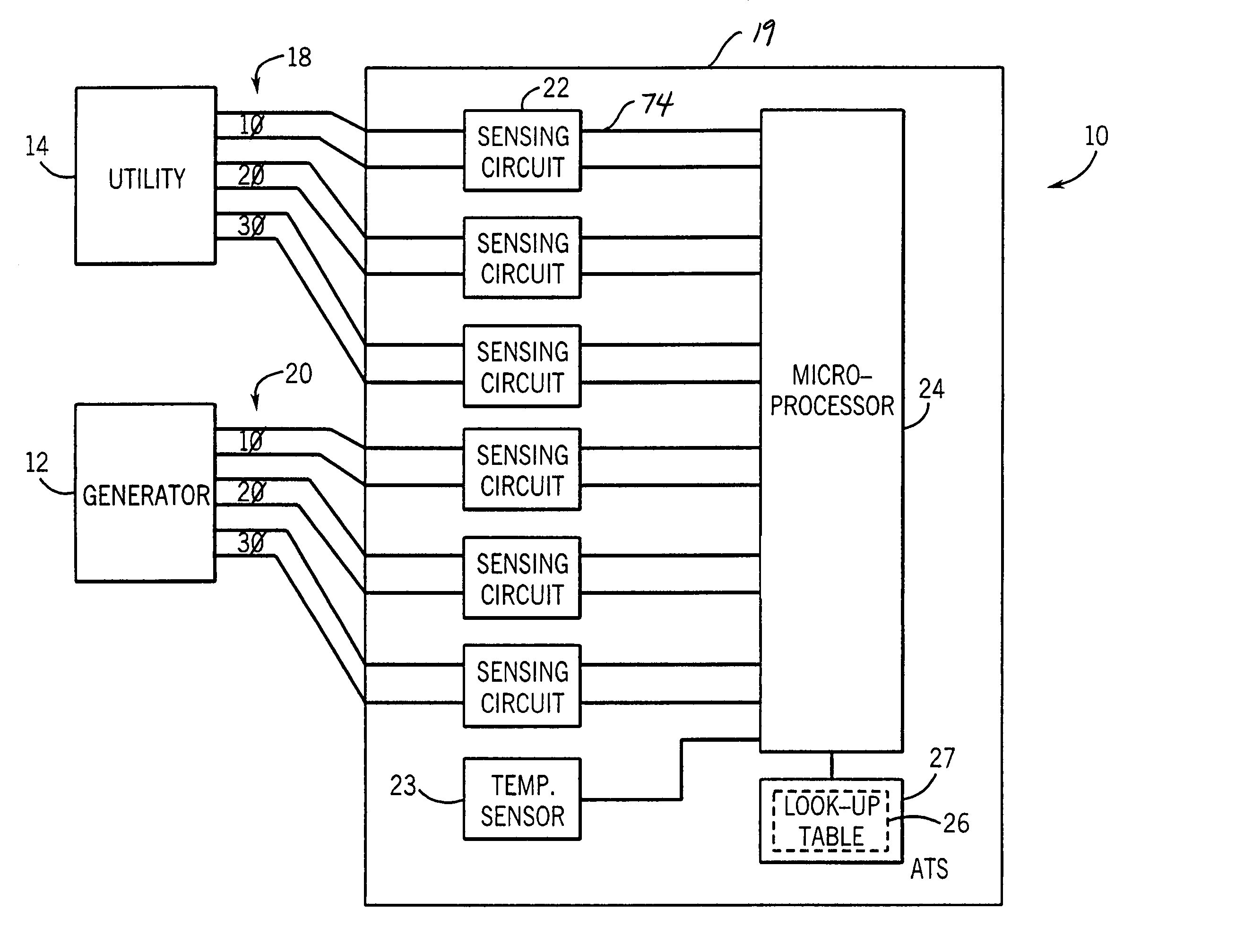
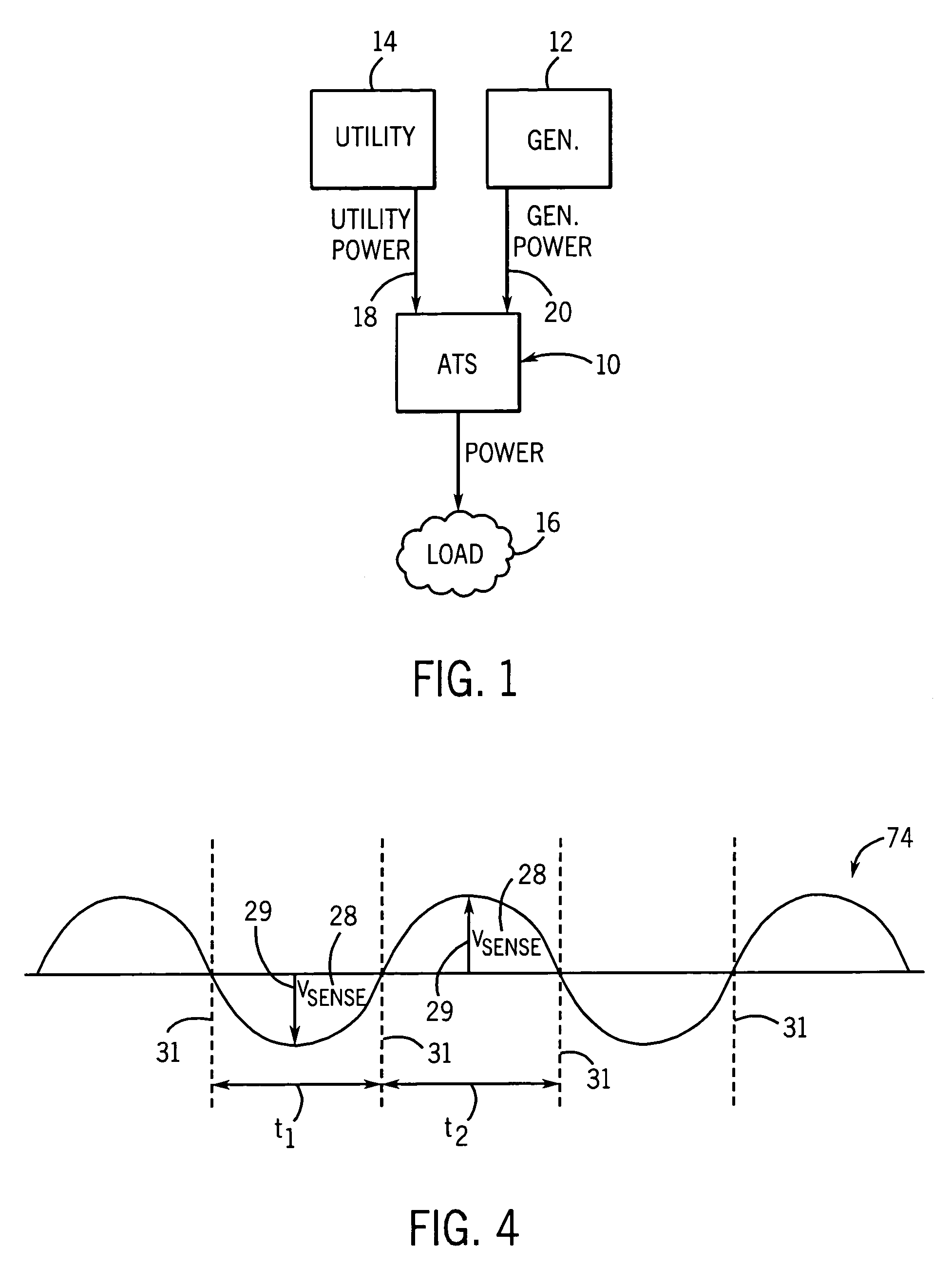
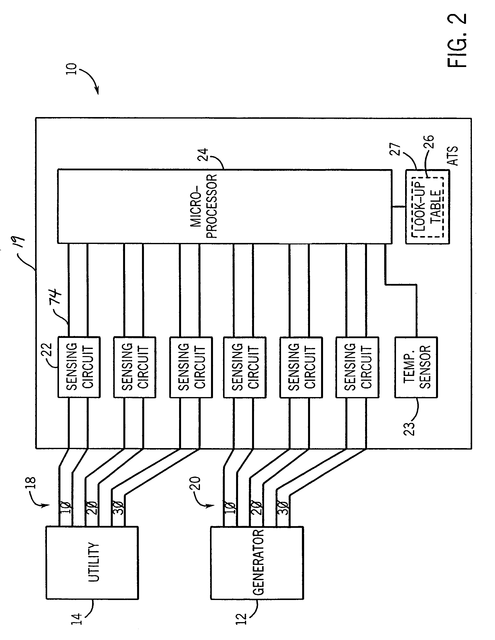
[0016]Referring now to the Figures and more particularly to FIG. 1 an automatic transfer switch 10 is shown electrically connected to receive utility-level input power from an AC power generator 12 and a utility power source 14. The automatic transfer switch (ATS) 10 senses the voltage input on the utility power line 18 from the utility power source 14, and switches power directed to the load 16 from the utility power line 18 to the generator power line 20 when the input voltage on the utility power line 18 from the utility power source 14 falls below a predetermined value. The predetermined value can be selected, for example, to prevent the load from being affected by a brown out or black out condition, or to optimize performance of the load. The ATS 10 also monitors the input voltage from the generator 12 and switches back to the utility power source 14 if the generator voltage falls due to, for example, a lack of fuel or other reasons. By continually monitoring the input from bot...


PUM


Abstract

An Automatic Transfer Switch System includes a control circuit in which high frequency transformers, designed to operate linearly in a frequency range above the operating frequency range of utility-level power, are employed for voltage sensing. An output signal from a high frequency line matching transformer is received by a microprocessor which evaluates the signal for both a voltage level and frequency and uses these values as indices to an empirically-derived look-up table which provides an actual voltage level to the microprocessor. The actual voltage value can then be evaluated by the microprocessor to determine if and when the power delivered to a load should be supplied by a first or a second power supply.

Description

BACKGROUND OF THE INVENTION[0001]The present invention is related to the field of power switching devices and more particularly to voltage sensing and regulation in an automatic transfer switch system.[0002]Automatic Transfer Switch (ATS) systems for switching between two or more power sources are well known in the art. ATS systems sense a voltage level provided by each of two or more AC power sources and automatically switch the power delivered to a load from a first AC power source to a second AC power source when the delivered voltage falls below a selected value. These systems are commonly provided, for example, between two or more AC power generators, between an AC power generator and a utility line, or in other combinations in which multiple AC power sources are used. Such systems are particularly useful in switching an appropriate alternate source of power into a system when there is a power drop or power failure situation, including blackout and brown out situations.[0003]AT...

Claims


Application Information

Patent Timeline
Patent Type & Authority Patents(United States)
IPC IPC(8): H01H35/00H02J9/06
CPCH02J9/06H02J2009/068H02J9/068
Inventor EATON, ZANE C.ALBSMEIER, ERIC
Owner KOHLER POWER SYST
Why Eureka
Try Eureka