Motor magnetic pole position estimation device and control device

a technology of motor magnetic pole position and estimation device, which is applied in the direction of motor/generator/converter stopper, electronic commutator, dynamo-electric converter control, etc., can solve the problem of methods that are hardly applied to general-purpose systems, and achieve the effect of fast response of the control system

Inactive Publication Date: 2007-01-02
YASKAWA DENKI KK
View PDF7 Cites 15 Cited by
  • Summary
  • Abstract
  • Description
  • Claims
  • Application Information

AI Technical Summary

Benefits of technology

[0009]In the conventional technique, however, the methods which estimate a magnetic pole position by using harmonics of an inverter output high frequency or high-frequency currents of carrier frequency components have a feature that, although high-frequency currents caused by high-frequency voltages disturb the voltage of the fundamental harmonic component of the inverter output, the carrier frequency is sufficiently higher than the rotational speed of a motor, and hence the high-frequency currents do not generate a torque disturbance. The methods have an advantage that the pole position estimation does not involve restrictions such as addition of a low-pass filter to a current feedback value, and also fast response of the control system is enabled. From the viewpoint of practical use, however, there is a problem in that the levels of high-frequency currents depend on parameters of motors, and hence the influence is not uniform according to motors, thereby causing the methods to be hardly applied to a general-purpose system.
[0010]Therefore, it is an object of the invention to provide an apparatus for estimating a magnetic pole position of a motor, and a controlling apparatus in which three-phase carriers having an arbitrary phase difference between phases in a PWM output are switched to a single-phase carrier, and a time period of implementing magnetic pole estimation is adjusted to enable the amplitudes of high-frequency currents to be adjusted, thereby enabling application to a general-purpose system.
[0016]The invention of claim 6 is characterized in that, in the apparatus for estimating a magnetic pole position of a motor according to claim 1, implementing time periods of the means 1 and the means 2 in the means for switching over the means 1 for producing an arbitrary phase difference in PWM carrier signals between respective two phases such as UV, VW, or WU of three or UVW phases, and the means 2 for causing the phase difference between two phases such as UV, VW, or WU of three or UVW phases to become zero are set for purposes of adjusting amplitudes of generated high-frequency currents, and reducing a power loss.

Problems solved by technology

From the viewpoint of practical use, however, there is a problem in that the levels of high-frequency currents depend on parameters of motors, and hence the influence is not uniform according to motors, thereby causing the methods to be hardly applied to a general-purpose system.

Method used


Image

  • Motor magnetic pole position estimation device and control device
  • Motor magnetic pole position estimation device and control device
  • Motor magnetic pole position estimation device and control device

Examples


Embodiment Construction

[0039]Hereinafter, an embodiment of the invention will be described with reference to the drawings.

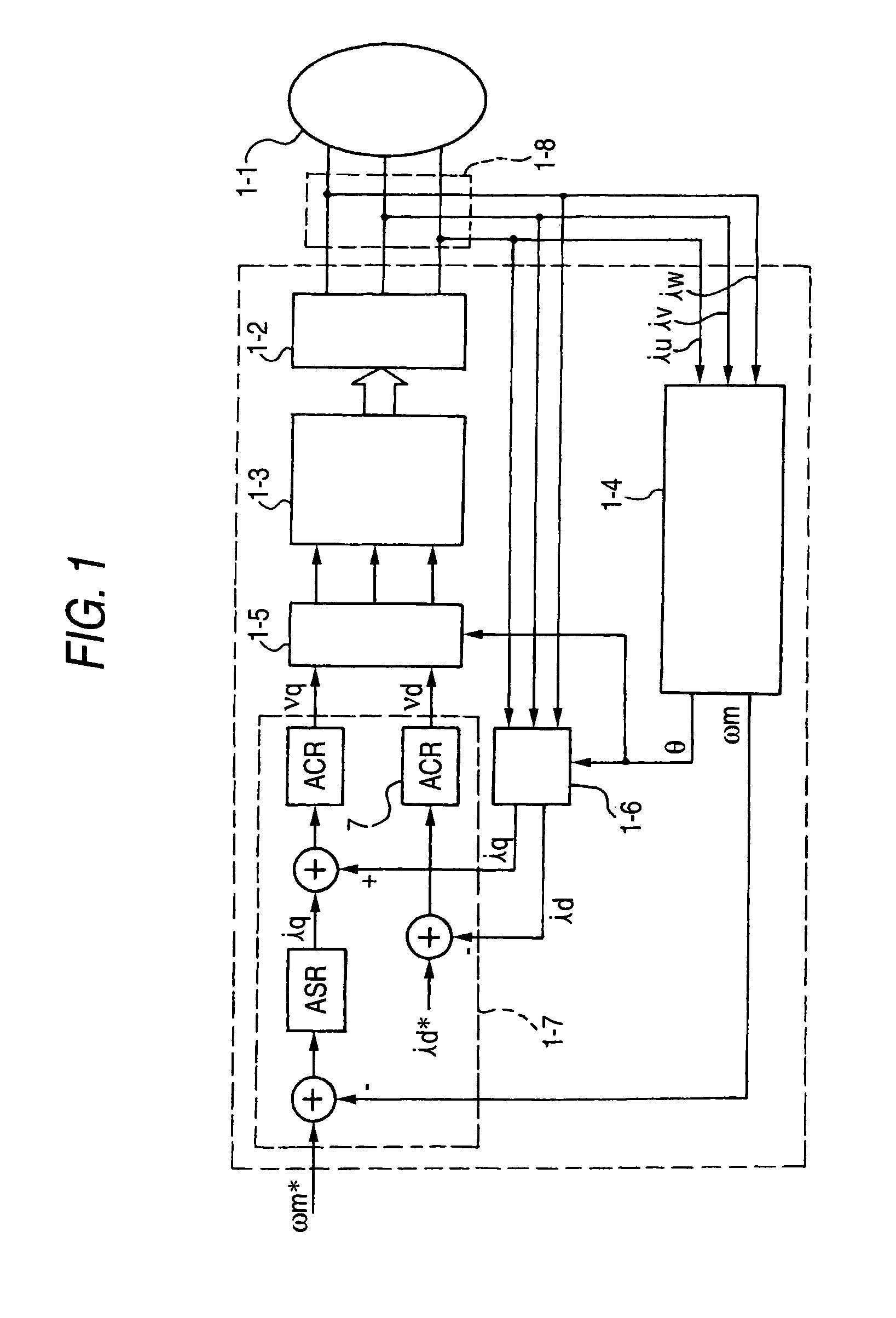
[0040]FIG. 1 is a block diagram of a sensorless speed controlling apparatus including the apparatus for estimating a magnetic pole position of a motor of an embodiment of the invention.

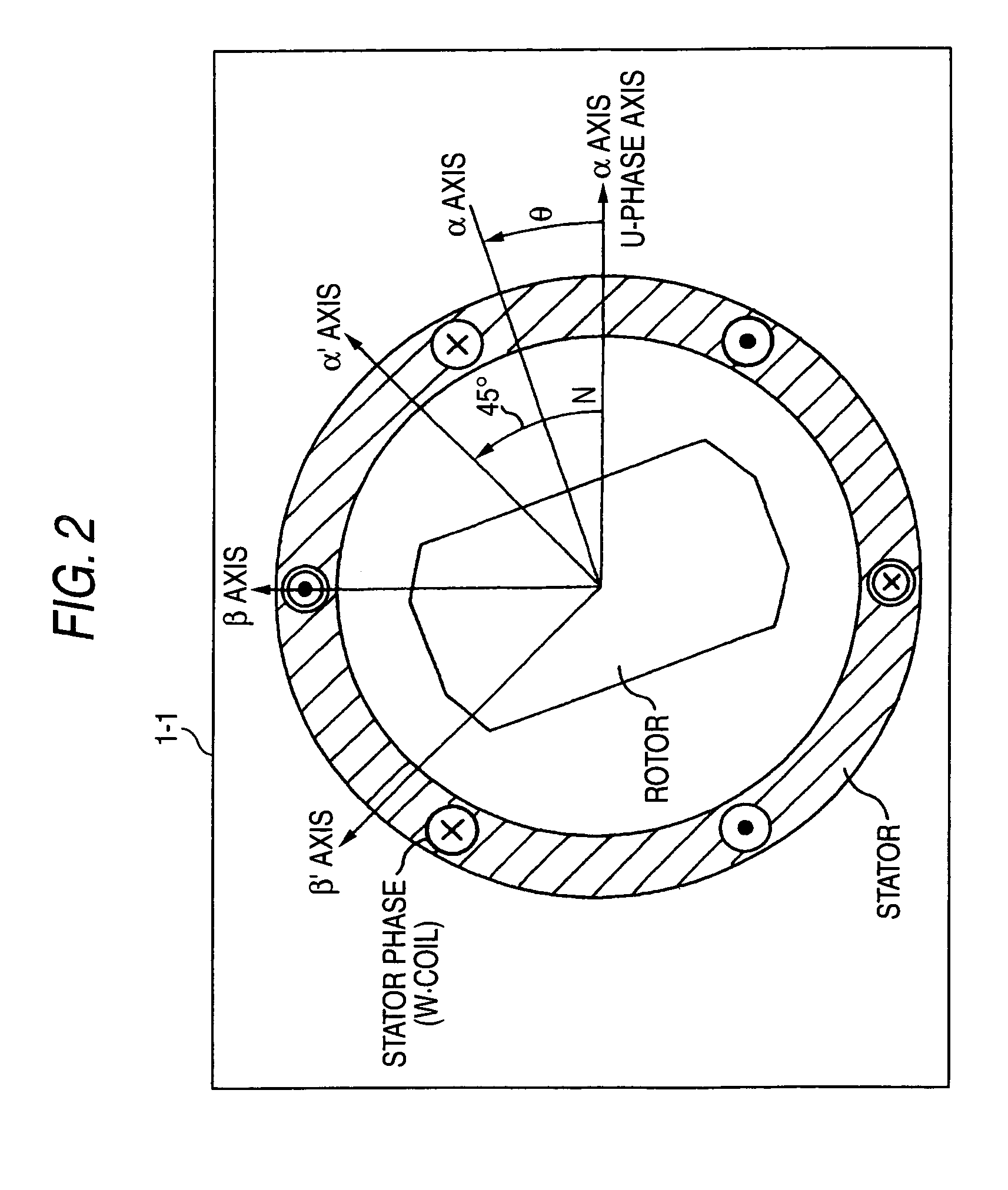
[0041]FIG. 2 is a model of a synchronous motor incorporating a permanent magnet shown in FIG. 1.

[0042]FIG. 3 is a waveform chart illustrating adjustment of an implementing time period in the apparatus for estimating a magnetic pole position shown in FIG. 1.

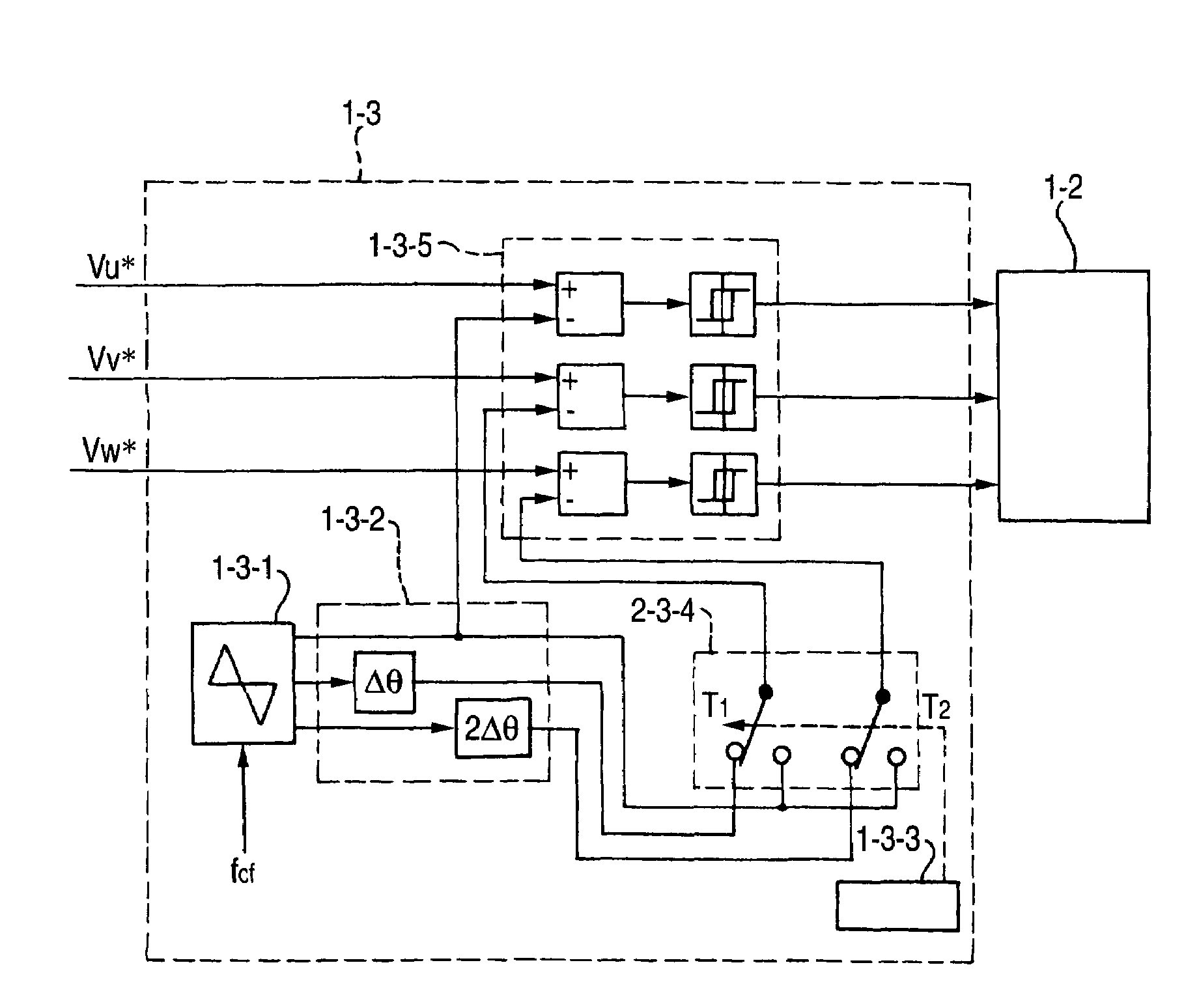
[0043]FIG. 4 is a block diagram of a PWM signal generating apparatus shown in FIG. 1.

[0044]FIG. 5 is a block diagram of a magnetic pole position / speed estimating apparatus shown in FIG. 1.

[0045]In FIG. 1, 1-1 denotes a motor incorporating a permanent magnet, 1-2 denotes a voltage source inverter, 1-3 denotes a PWM signal generating apparatus, 1-4 denotes a magnetic pole position / speed estimating apparatus, 1-5 and 1-6 denote two to three-phase converte...


PUM


Abstract

It is an object of the invention to provide an apparatus for estimating a magnetic pole position of a motor in which the amplitudes of high-frequency currents can be adjusted.In the invention, a controlling apparatus for driving a motor (1-1) by a voltage source PWM inverter (1-2), and controlling a torque and speed, or torque, speed, and position of the motor has: means for switching over first means for producing an arbitrary phase difference in PWM carrier signals between respective two phases such as UV, VW, or WU of three or UVW phases, and second means for causing the phase difference between two phases such as V, VW, or WU of three or UVW phases to become zero; means for extracting high-frequency currents in a same frequency band as carrier signals generated by it, from estimated currents; and means (1-4) for estimating a magnetic pole position by using the extracted high-frequency currents.

Description

TECHNICAL FIELD[0001]The present invention relates to an apparatus for controlling a motor which accurately estimates a magnetic pole position at a very low speed including zero speed, and which controls the torque, the speed, and the position on the basis of the estimated magnetic pole position.BACKGROUND ART[0002]As a conventional method of estimating a magnetic pole position, widely used is a method in which an induced voltage that is proportional to a motor speed is calculated from a motor input voltage and a current, and the speed is estimated, such as that reported in “Adaptive Current Control Method for Brushless DC motor with Function of Parameter Identification” IEEJ Transactions on Industry Applications, Vol. 108 No. 12, 1988. Also known is “Zero Speed Torque Control of Sensorless Salient-Pole Synchronous Motor” 1996 National Convention of IEEJ Industry Applications Society No. 170. In this technique, an AC signal is superimposed on a voltage command value, and an estimate...

Claims


Application Information

Patent Timeline
Patent Type & Authority Patents(United States)
IPC IPC(8): H02P6/18H02P6/16H02P6/06H02P6/08H02P6/17H02P6/28
CPCH02P6/185
Inventor IDE, KOZOSAWAMURA, MITSUJIROWOGARI, MENGESHA MAMOOYAMA, JUN
Owner YASKAWA DENKI KK
Why Eureka
Try Eureka