Device for locating and identifying circuit breakers

a circuit breaker and device technology, applied in the direction of measuring devices, electrical testing, instruments, etc., can solve the problems of inconvenient user rotation of the receiver, difficulty in seeing light,

a circuit breaker and device technology, applied in the direction of measuring devices, electrical testing, instruments, etc., can solve the problems of inconvenient user rotation of the receiver, difficulty in seeing light,

US7157896B2Inactive Publication Date: 2007-01-02POWER PROD

Image

  • Device for locating and identifying circuit breakers
  • Device for locating and identifying circuit breakers
  • Device for locating and identifying circuit breakers

Examples


Embodiment Construction

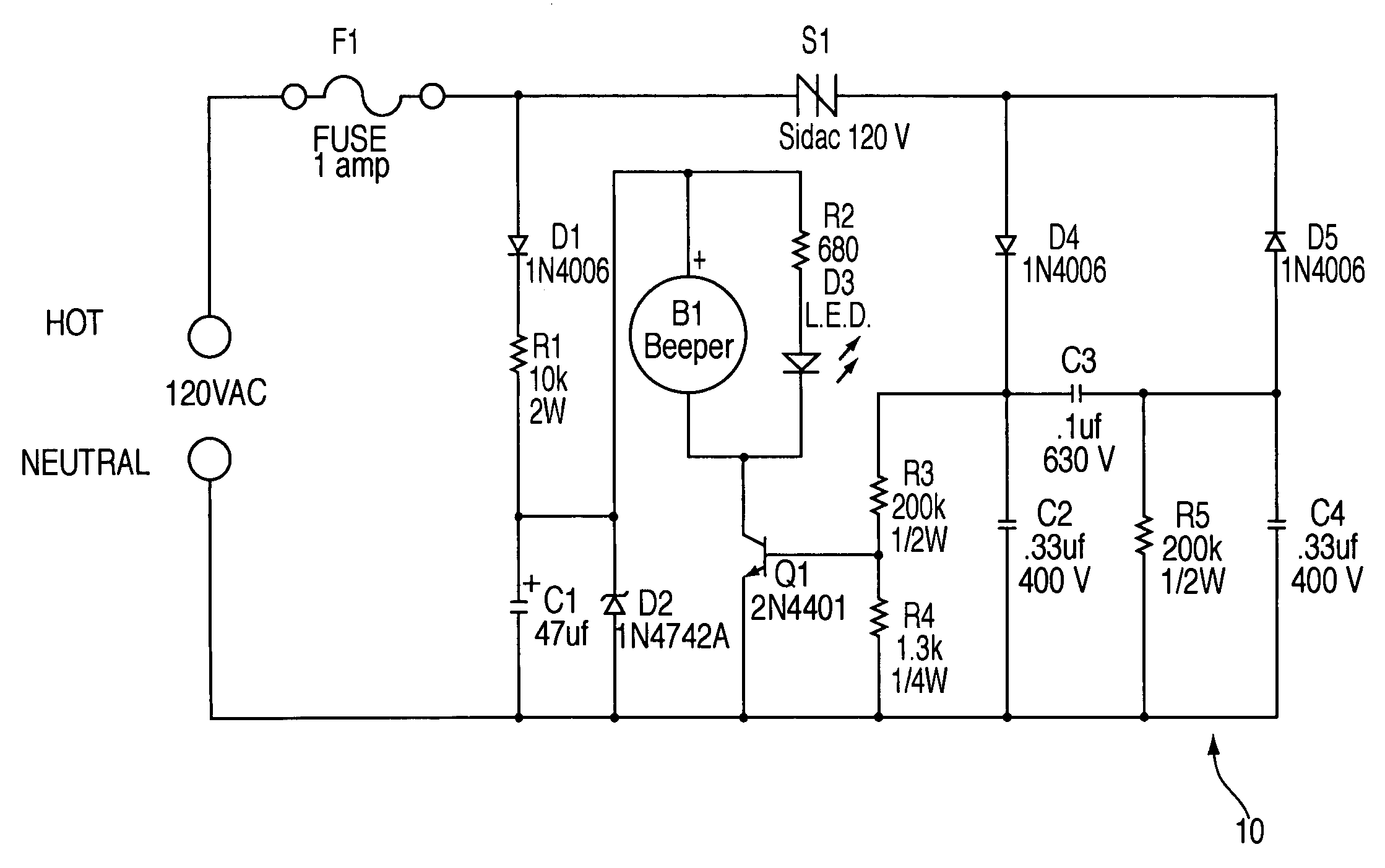
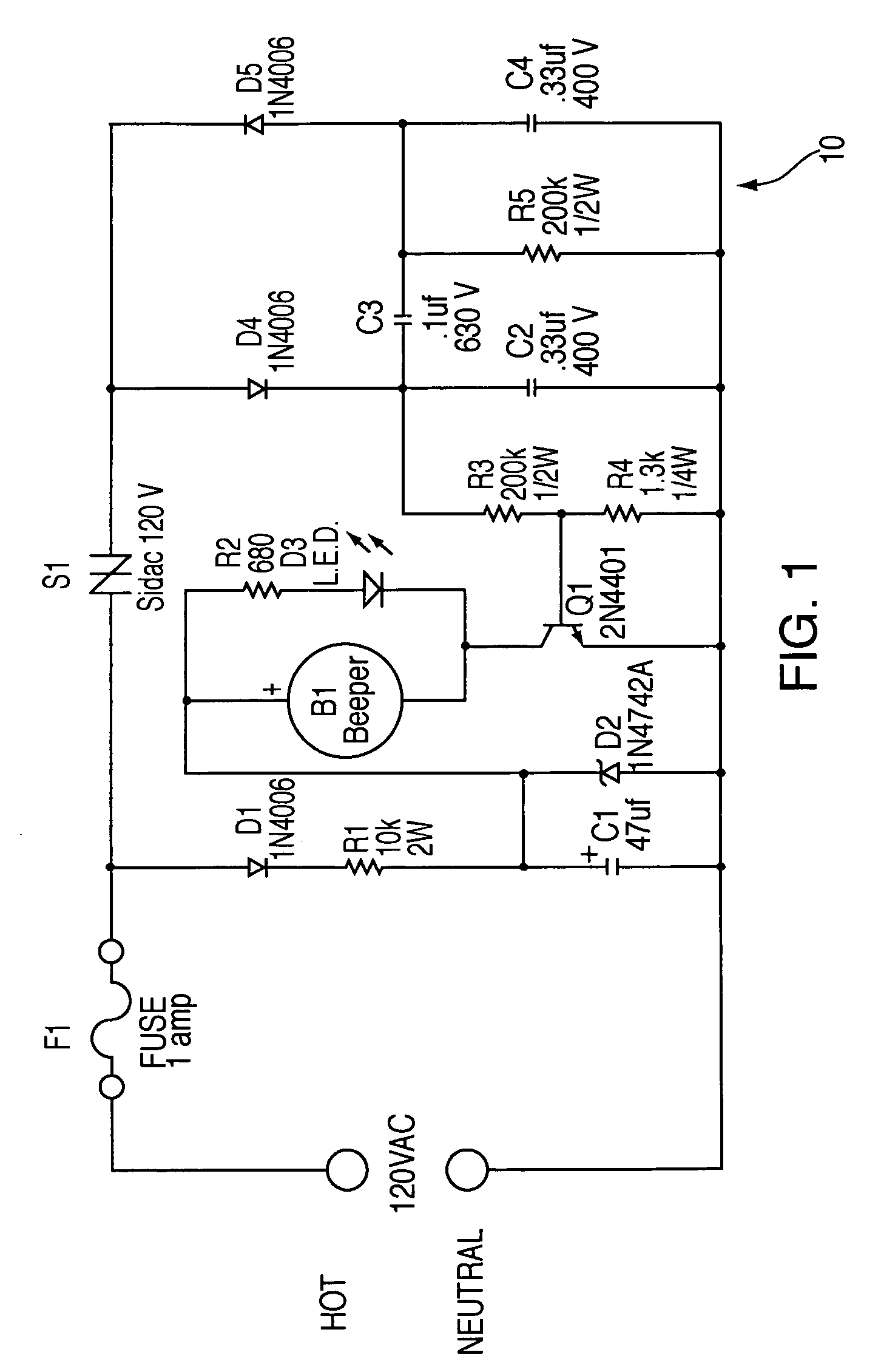
[0020]With reference to the drawings, wherein the same reference number indicates the same element throughout, there is shown in FIG. 1 a schematic of the pulse-generating transmitter 10. Transmitter 10 is adapted for use with a standard AC receptacle powered from one of the branch circuits supplied by a circuit breaker panel.

[0021]Transmitter 10

[0022]AC line voltage is applied to fuse F1, the junction of F1, S1 and D1 have Hot AC line voltage present with respect to the AC Neutral return connection. The series combination of D1 and R1 form a half wave current limited source for charging capacitor C1, the magnitude of this voltage is limited by zener diode D2. The resulting voltage at the junction of R1, C1, and D2 produces a DC supply for powering beeper B1 and light emitting diode (LED) D3, current through LED D3 is further limited by resistor R2. Transistor Q1 is configured as a voltage controlled switch, when this switch is in conduction its collector emitter creates a path to c...


PUM


Abstract

The transmitter of the circuit breaker locator draws large amplitude, short duration, phase locked unipolar pulses of current from the power source at a frequency lower than that of the AC line frequency. The audible and visual indicators of the transmitter are triggered at the rate of the current pulses drawn from the AC line. The receiver of the circuit breaker locator has a pick-up coil that responds to magnetic field surrounding the circuit breaker, an amplifier for boosting the signal from the pick-up coil, and a single shot pulse stretcher triggered by the amplifier. The pulse stretcher drives both audible and visual signals, and at the same time charges a memory capacitor in a staircase generator fashion. The magnitude of the memory capacitor voltage in turn controls the gain of the amplifier. A switch controls the voltage applied to the amplifier, which increases by a predetermined amount when released.

Description

FIELD OF THE INVENTION[0001]The present invention relates to power line testing equipment and more particularly to the identification of the circuit breakers supplying power to a particular branch circuit and AC outlets.BACKGROUND OF THE INVENTION[0002]When working on the electrical wiring of a home or building, it is desirable, and necessary for safety purposes to shut off the circuit breaker supplying power to a particular electrical outlet. Circuit breaker panels typically have a plurality of circuit breakers supplying power to many areas of the home. Many times, the branches these circuit breakers control are not clearly marked, and often the markings are only general in nature. Because of the marking system employed on almost all circuit breaker panels, the person desiring to remove power to a particular branch circuit or AC power outlet usually turns off many circuit breakers in the process of trying to locate the correct one. During this trial and error period, power could be...

Claims


Application Information

Patent Timeline
02 Jan 2007
Publication
US7157896B2
IPC
G01R19/00
CPC
G01R19/16547
Inventors
KONOPKA, JOHN G.