Displacement sensor with inner and outer winding sections

a displacement sensor and inner and outer winding technology, applied in the field of sensor coils, can solve the problems of unsatisfactory ratio of measuring range to overall length of the sensor, inability to meet the requirements of the measurement device, and limited space, so as to achieve the effect of reducing the measurement range, and reducing the measurement distan

Inactive Publication Date: 2007-01-02
MICRO EPSILON MESSTECHNIK GMBH & CO KG
View PDF5 Cites 0 Cited by
  • Summary
  • Abstract
  • Description
  • Claims
  • Application Information

AI Technical Summary

Benefits of technology

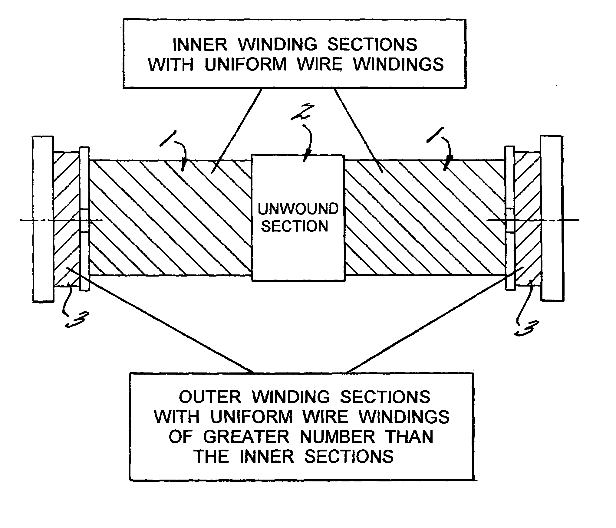
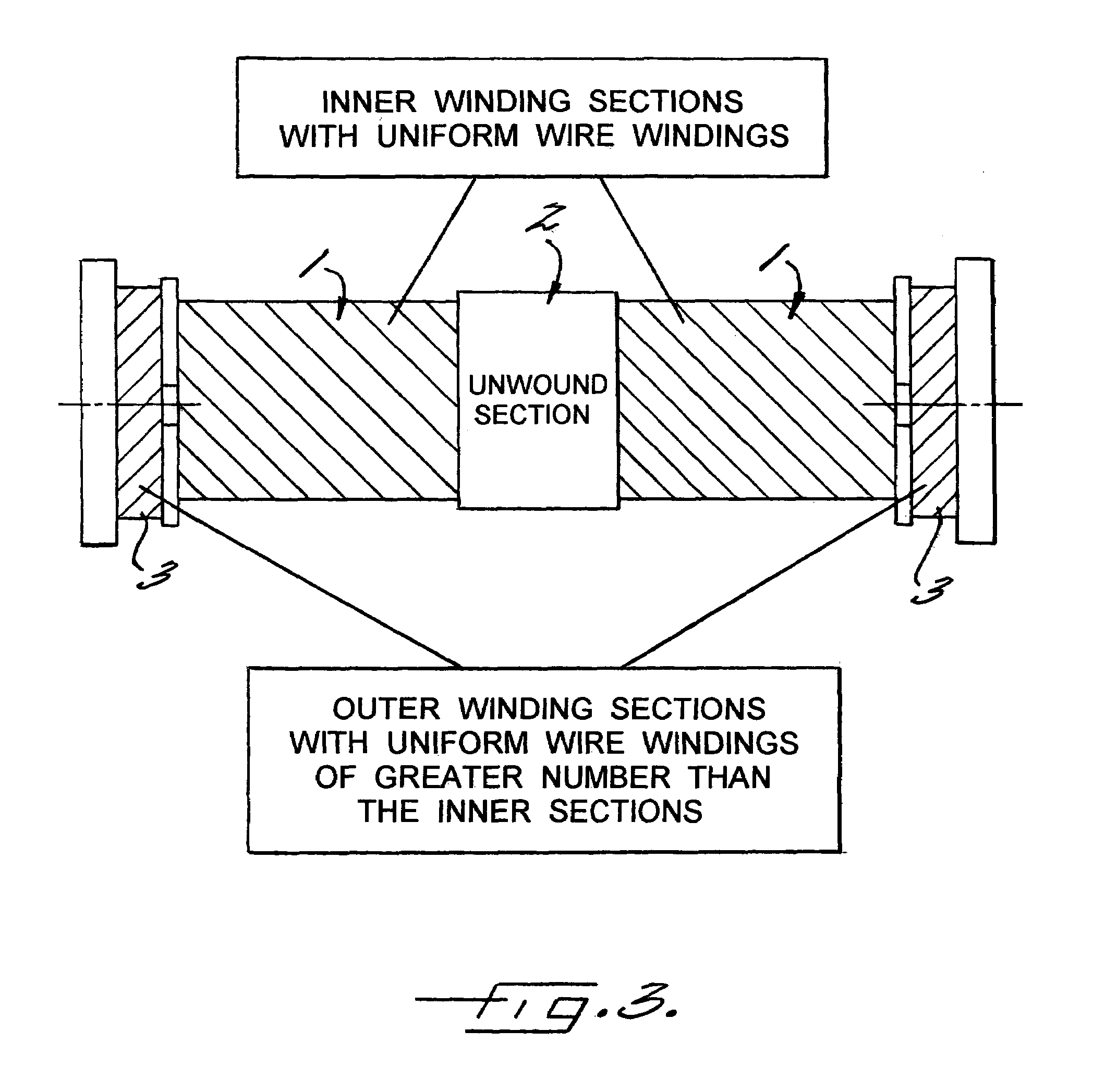
[0015]In accordance with the invention, it has been found that one can avoid an inhomogeneous winding of the sensor coil, and thus avoid the use of costly coil winding machines, when the initially provided inner winding sections are formed by a homogeneous or conventional winding, i.e., a winding with a uniform axial spacing between the coils. A comparable characteristic of the electromagnetic field of the sensor coil as disclosed in DE 41 28 159 A1 is achieved by providing two additional, substantially identically formed outer winding sections that have a larger number of windings than the two inner winding sections. As a result, the electromagnetic field of the sensor coil according to the invention is made weaker in the center region because of an unwound section that is provided in this region. In the outer region of the sensor coil according to the invention, the electromagnetic field is made stronger because of the two outer winding sections with the larger number of windings. This permits realizing in an advantageous manner, at least in sections, a substantially linear course of the resultant measuring signal.
[0034]The compact size of the sensor coil, a simple winding concept, and a very simple, electrical interface show the economic advantages of the sensor coil and the displacement sensor for applications with small, medium, and large piece numbers.

Problems solved by technology

Also, another typical requirement on the part of the industry lies in constructing the displacement sensors as compactly as possible in the case of a predetermined measuring range, since the available mounting space is very limited in many cases.
This requirement often cannot be met to an adequate extent by the sensors that are currently offered on the market and normally used for short displacement measurements, such as, for example, differential chokes or differential transformers.
Disadvantageous in these so-called differential systems is the unfavorable ratio of measuring range to overall length of the sensor, i.e., the overall length of the sensor is normally by a multiple greater than the measuring range.
In practice, the conversion of the concept of the measuring device disclosed in DE 41 28 159 A1 is complicated and can be realized only with costly manufacturing methods, since the inhomogeneous winding is realizable only with special, costly coil winding machines and only with extensive programming requirements.
Thus, it is not possible to realize in small piece numbers an economic production of sensor coils with different characteristics, for example, different windings.

Method used


Image

  • Displacement sensor with inner and outer winding sections
  • Displacement sensor with inner and outer winding sections
  • Displacement sensor with inner and outer winding sections

Examples


Embodiment Construction

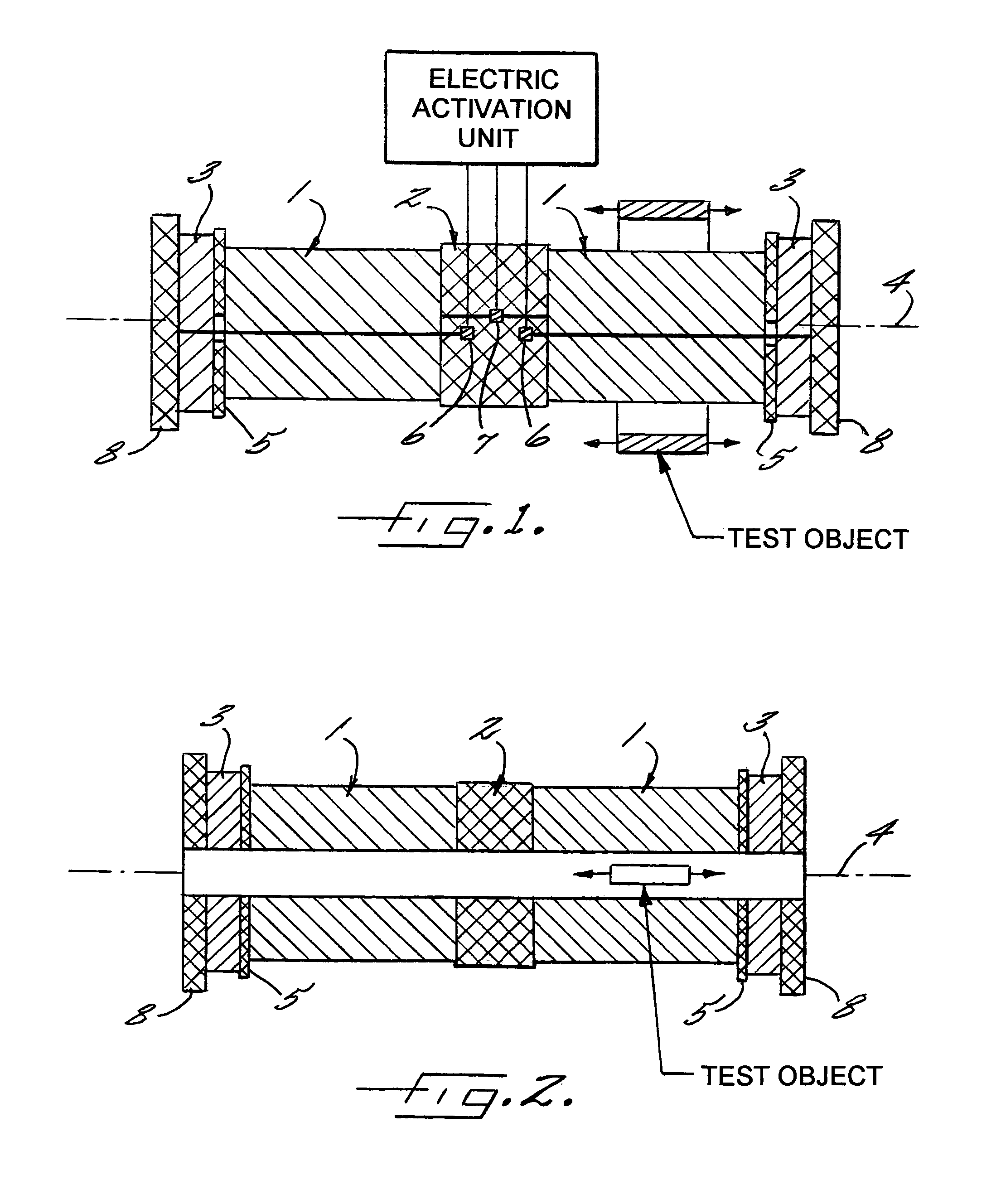
[0039]FIG. 1 shows a sensor coil having an annular test object which surrounds the coil, The coil has two inner, substantially identically formed winding sections 1 which are realized in the form of winding chambers. Between the two inner winding sections 1, an unwound section 2 is provided.

[0040]In accordance with the invention, two outer, substantially identically formed winding sections 3 are provided, which are respectively arranged at the ends of the two inner winding sections 1 that face away from the unwound section 2. The two outer winding sections 3 have a larger number of windings than the two inner winding sections 1. Thus, the sensor coil of the invention is constructed to be symmetrical, i.e. symmetrical with respect to the unwound section 2.

[0041]The length of each outer winding section 3 in the direction of the longitudinal axis 4 of the sensor coil, which is shown in phantom lines, is made shorter than the length of the inner winding sections 1. Since the outer windi...


PUM


Abstract

A sensor coil for a non-contacting inductive displacement sensor, having two inner substantially identically formed winding sections (1), with an unwound section (2) provided between the two inner winding sections. Also, the coil has two outer substantially identically formed winding sections (3), which are respectively arranged at the ends of the two inner winding sections (1) facing away from the unwound section (2). The two outer winding sections (3) have a larger number of windings than the two inner winding sections (1), thereby producing a measuring signal which is substantially linear along the measuring range.

Description

CROSS REFERENCE TO RELATED APPLICATION[0001]The present application is a continuation of international application PCT / DE03 / 001201, filed 10 Apr., 2003, and which designates the U.S. The disclosure of the referenced application is incorporated herein by reference.BACKGROUND OF THE INVENTION[0002]The present invention relates to a sensor coil, in particular for a non-contacting inductive displacement sensor, of the type composed of two, substantially identically formed winding sections, with an unwound section being provided between the two winding sections.[0003]For the purposes of the present invention, a winding section means that a corresponding number of windings of a coil wire are wound over a defined section of the sensor coil. Concretely, it could be, for example, a winding chamber, which can be slid onto a coil form in the way a module. Within the scope of the present invention, the two winding sections are further developed such that they are surrounded by other components,...

Claims


Application Information

Patent Timeline
Patent Type & Authority Patents(United States)
IPC IPC(8): G01B7/14G01D5/22G01D5/20
CPCG01D5/22G01D5/2013
Inventor WEBER, MARKUS
Owner MICRO EPSILON MESSTECHNIK GMBH & CO KG
Why Eureka
Try Eureka