

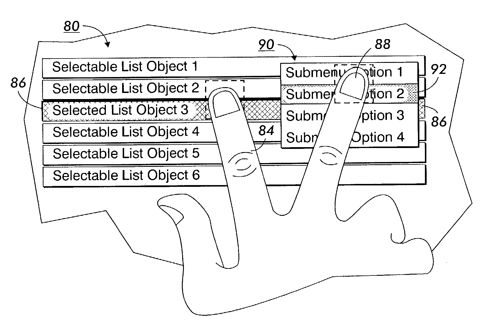
Secondary touch contextual sub-menu navigation for touch screen interface
a technology of contextual submenu navigation and touch screen interface, which is applied in the direction of instruments, electrographic process devices, computing, etc., can solve the problems of toggling action and difficulty in making selections
- Summary
- Abstract
- Description
- Claims
- Application Information
AI Technical Summary
Benefits of technology
Problems solved by technology
Method used
Image

Examples
Embodiment Construction
[0017]It will become evident from the following discussion that embodiments of the present application set forth herein, are suited for use in a wide variety of printing and copying systems, and are not necessarily limited in application to the particular systems illustrated.
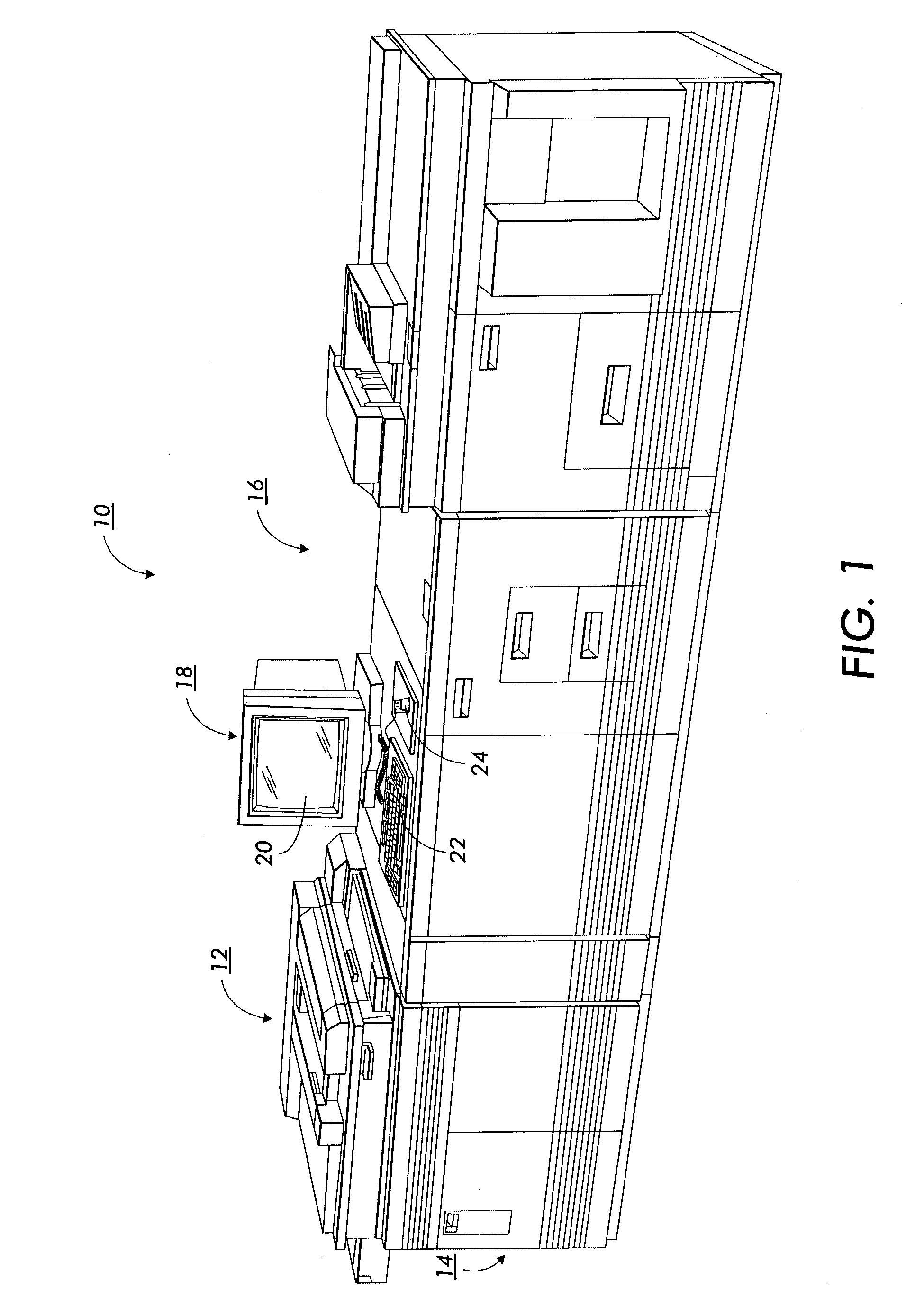
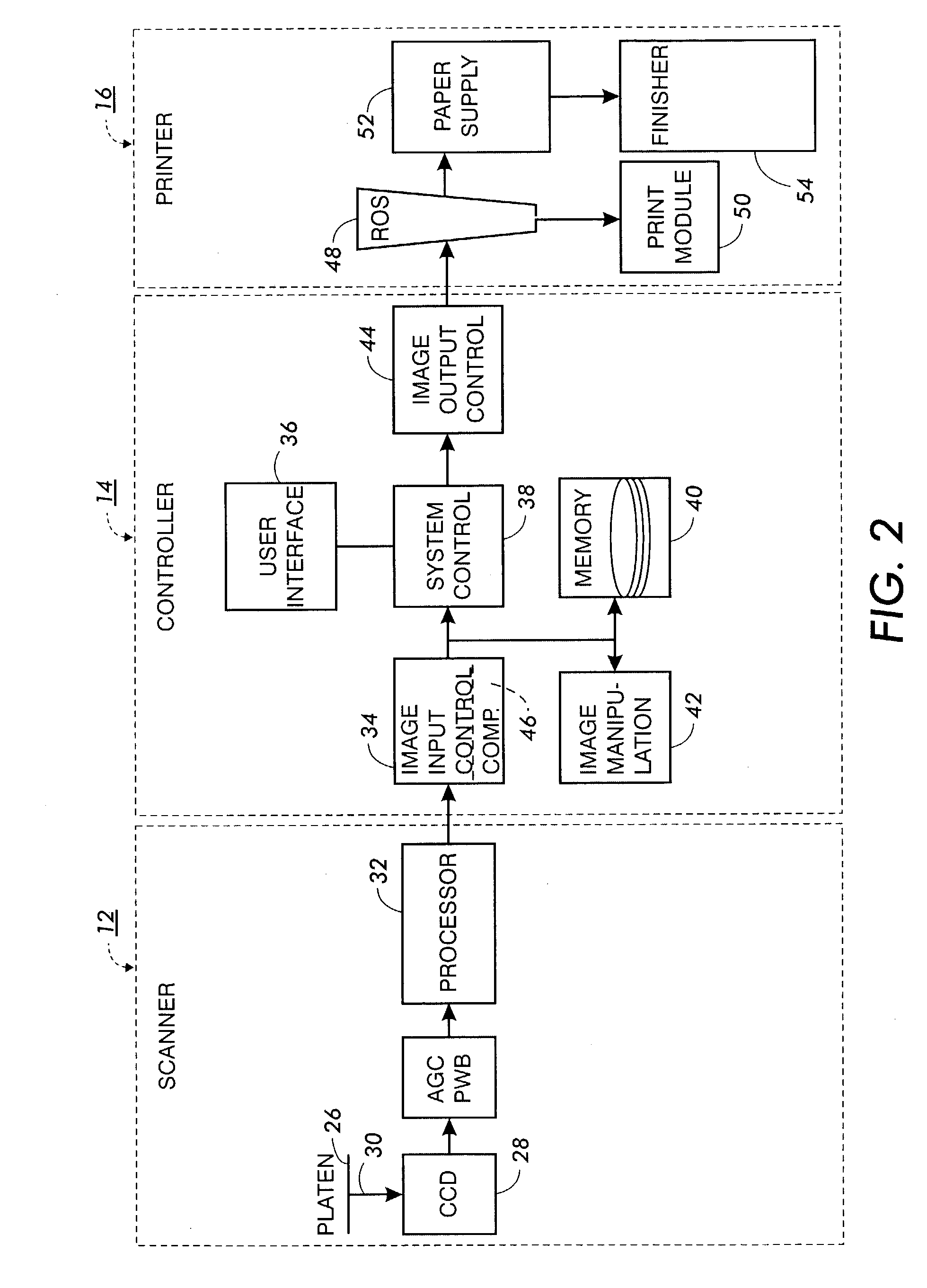
[0018]With reference to the drawings, where the showings are for the purpose of illustrating an embodiment of the invention and not for the purpose of limiting same, FIG. 1 shows an exemplary laser based printing system 10 for processing print jobs in accordance with the teachings of the present invention. Printing system 10 includes a scanner section 12, controller section 14, and printer section 16. While a specific printing system is shown and described, the present invention may be used with other types of printing systems such as, e.g., ink jet, ionographic, etc.
[0019]The printing system 10 further includes a User Interface (UI) 18 having a combined operator controller / CRT display comprising an interactive ...
PUM
 Abstract
Description
Claims
Application Information