Tape printer

A belt printer and print head technology, which is applied in typewriters, printing devices, printing, etc., can solve the problems of increasing costs, and achieve the effect of avoiding damage to printing belts and ribbons

Active Publication Date: 2006-09-06
BROTHER KOGYO KK
View PDF0 Cites 93 Cited by
  • Summary
  • Abstract
  • Description
  • Claims
  • Application Information

AI Technical Summary

Problems solved by technology

[0005] However, there is a known risk in the tape printer of the above publication that, when the tape printer is stored for a long time, the platen roller and the print head stick to each other due to the contact between the platen roller and t

Method used


Image

  • Tape printer
  • Tape printer
  • Tape printer

Examples


Embodiment Construction

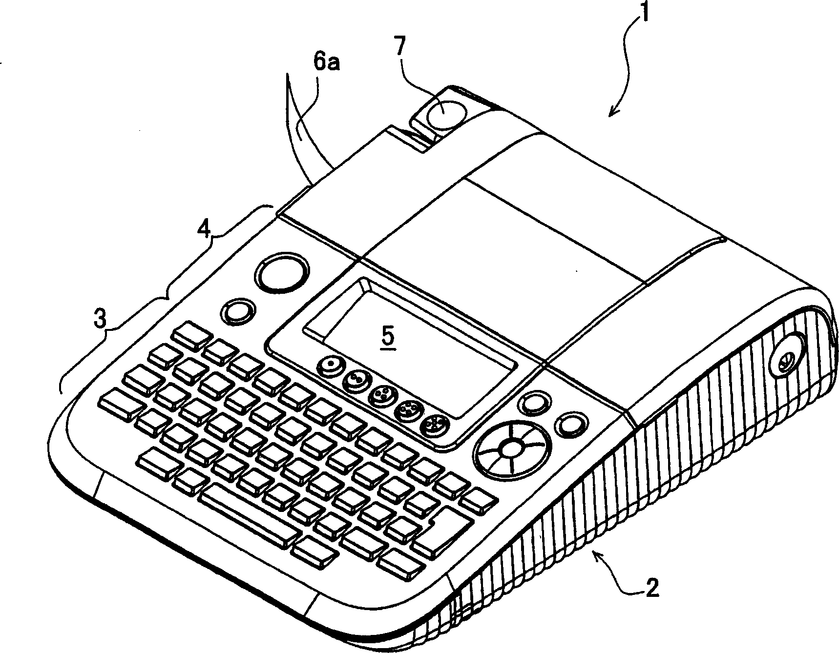
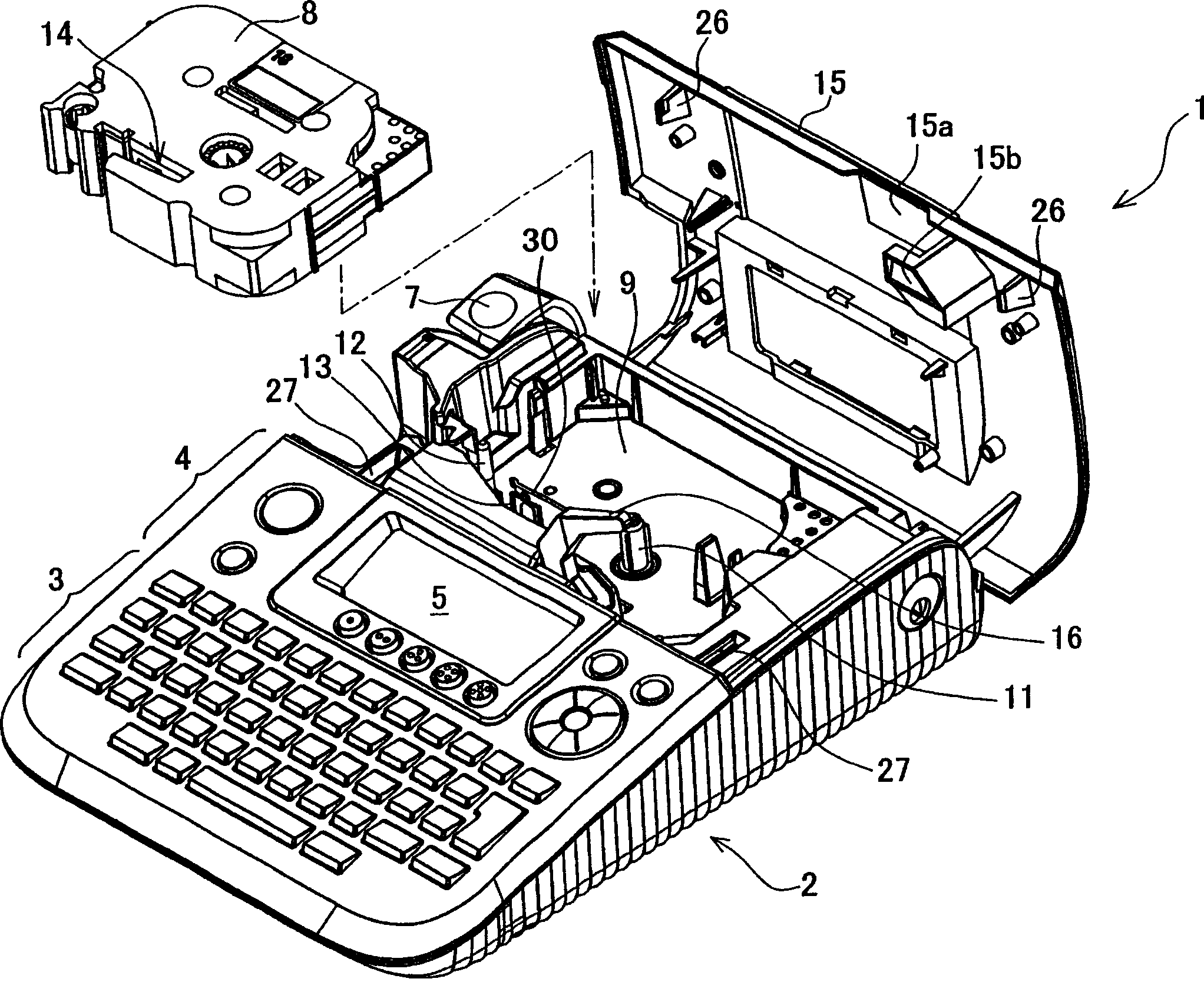
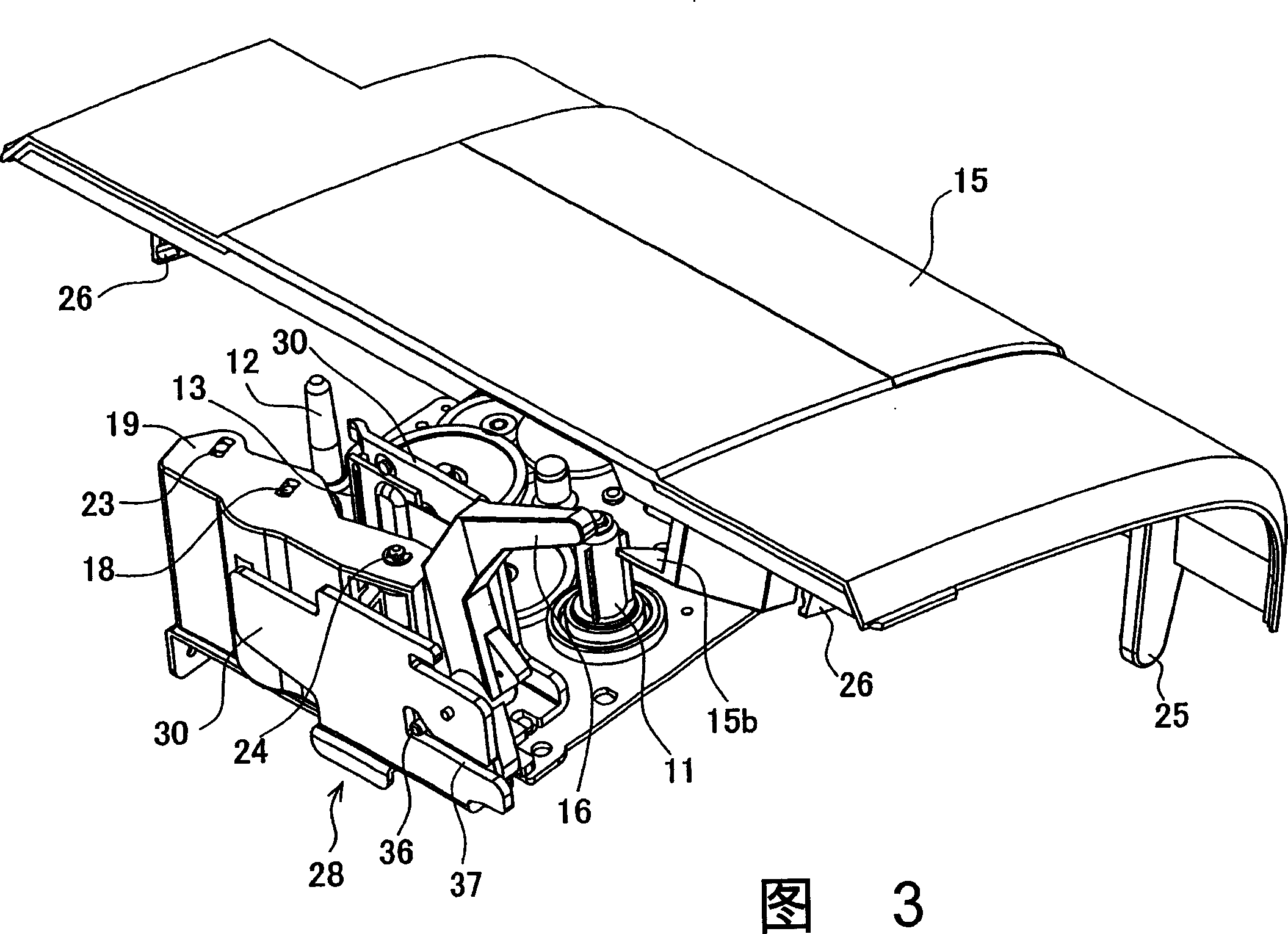
[0027] A first aspect embodying the tape printer of the present invention will now be described in detail with reference to the accompanying drawings. First, refer to Figures 1 to 4 A schematic structure of the tape printer of the first aspect is explained. figure 1 is an external view of the tape printer according to the first aspect of the present invention. figure 2 is a perspective view of a tape printer with an open cover element. Figure 3 is an enlarged perspective view of the cover member and a printing mechanism. Figure 4 is an explanatory diagram of the relationship between a cassette and a printing mechanism branch.

[0028] like figure 1 As shown, the tape printer 1 of the first aspect is provided with a keyboard 3 , function keys 4 , a liquid crystal display (hereinafter referred to as “LCD”) 5 and a knife lever 7 . A keyboard 3 for inputting various characters is provided on a top surface of a main body 2 . Above the keyboard 3, various function keys 4 ar...


PUM


Abstract

It is intended to provide a tape printer which enables to forcibly separate a platen roller and a print head along with an opening movement of a cover element in case the platen roller and the print head have adhered to each other because of a long-period storage of the tape printer with the platen roller and the print head being in contact. Accordingly, a cam pressing member and a cam receiver move a roller holder to a withdrawing position in which the platen roller and a thermal head are separated from each other when the cover element is opened, so that the cam pressing member and the cam receiver can be forcibly returned to the withdrawing position from a position in which the platen roller is in contact with the thermal head.

Description

technical field [0001] The present invention relates to a tape printer, in particular, to a tape printer capable of forcibly separating a platen roller and a print head accompanied by an opening movement of a cover member, because the The platen roller and the printhead stick to each other due to the contact between the platen roller and the printhead in the case of storing the tape printer. Background technique [0002] Conventionally, there have been proposed various types of tape printers which print on a long printing tape of a printing medium, displaying a text consisting of characters input with an input device such as a keyboard. In tape printers, the printing tape is usually supplied from a tape cassette in which the printing tape and the ink ribbon are wound on respective spools and housed in a predetermined shaped cassette. [0003] A print head for printing on a printing tape and a platen roller for feeding the tape are provided in the cassette housing portion of...

Claims


Application Information

Patent Timeline
IPC IPC(8): B41J25/312B41J3/36B41J29/00
CPCB41J2/325
Inventor 山本稔东孝志
Owner BROTHER KOGYO KK
Why Eureka
Try Eureka