Switch contact for a planar inverted F antenna

a planar inverted f antenna and switch contact technology, applied in the direction of resonant antennas, substation equipment, transmission, etc., can solve the problem that the pogo pin is usually too expensive for mass production

Inactive Publication Date: 2002-07-23
CENTURION WIRELESS TECH INC +1
View PDF7 Cites 81 Cited by
  • Summary
  • Abstract
  • Description
  • Claims
  • Application Information

AI Technical Summary

Benefits of technology

to provide an improved switch contact for a wireless communication device including a printed circuit board and a planar inverted F antenna arranged parallel to the printed circuit board and spaced therefrom.

Problems solved by technology

A major difficulty encountered in mass production of a PIFA is the method used to inexpensively provide a connection between the signal on the printed circuit board (PCB) to the feed point on the PIFA.
However, pogo pins are usually too expensive for use in mass production.
Unfortunately, the spring portion of the contact is not enclosed to eliminate the induction.

Method used


Image

  • Switch contact for a planar inverted F antenna
  • Switch contact for a planar inverted F antenna
  • Switch contact for a planar inverted F antenna

Examples


Embodiment Construction

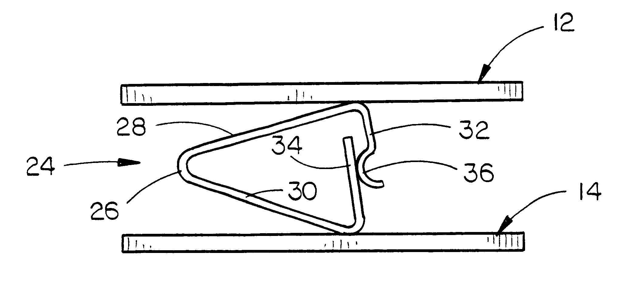
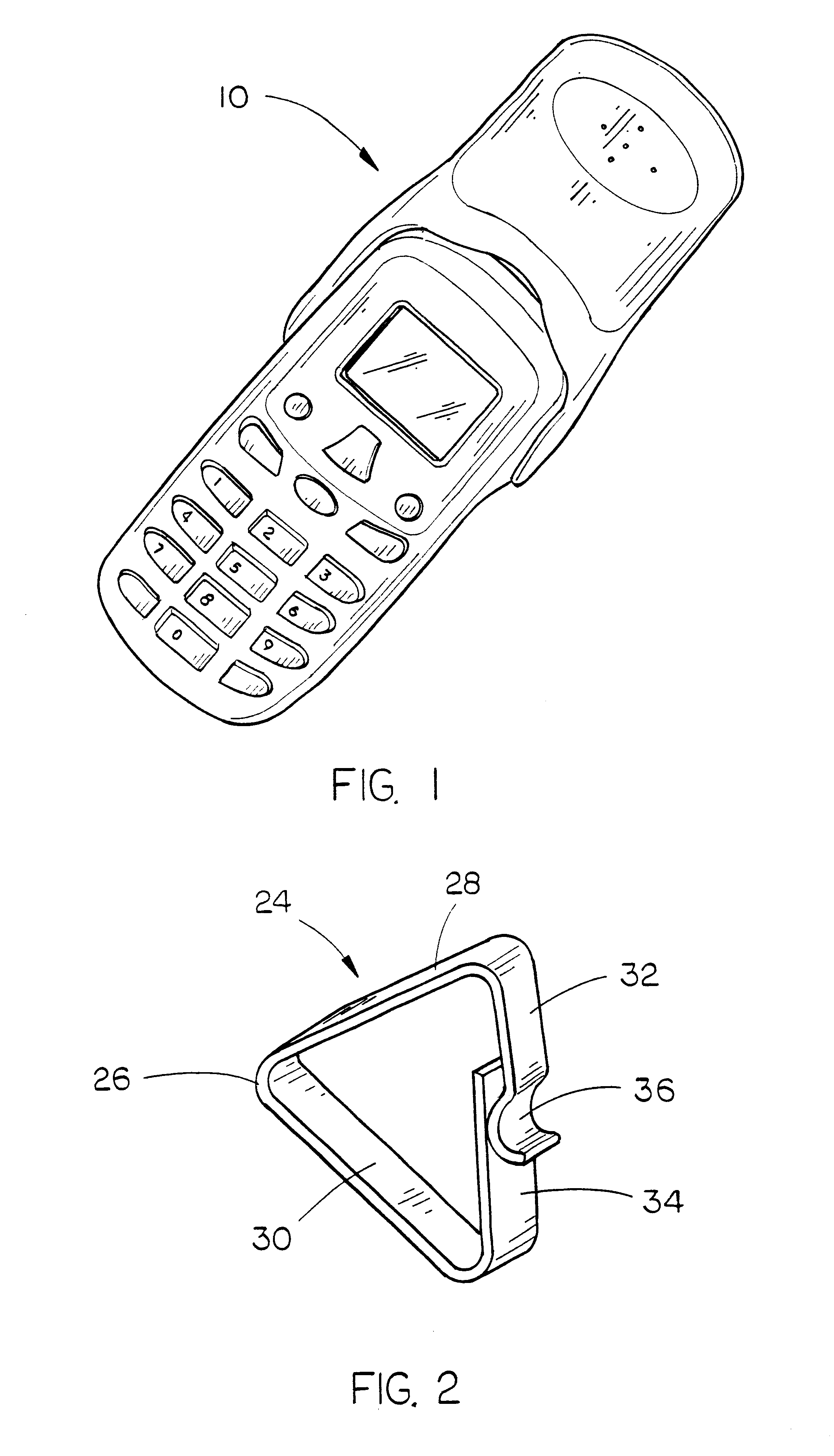
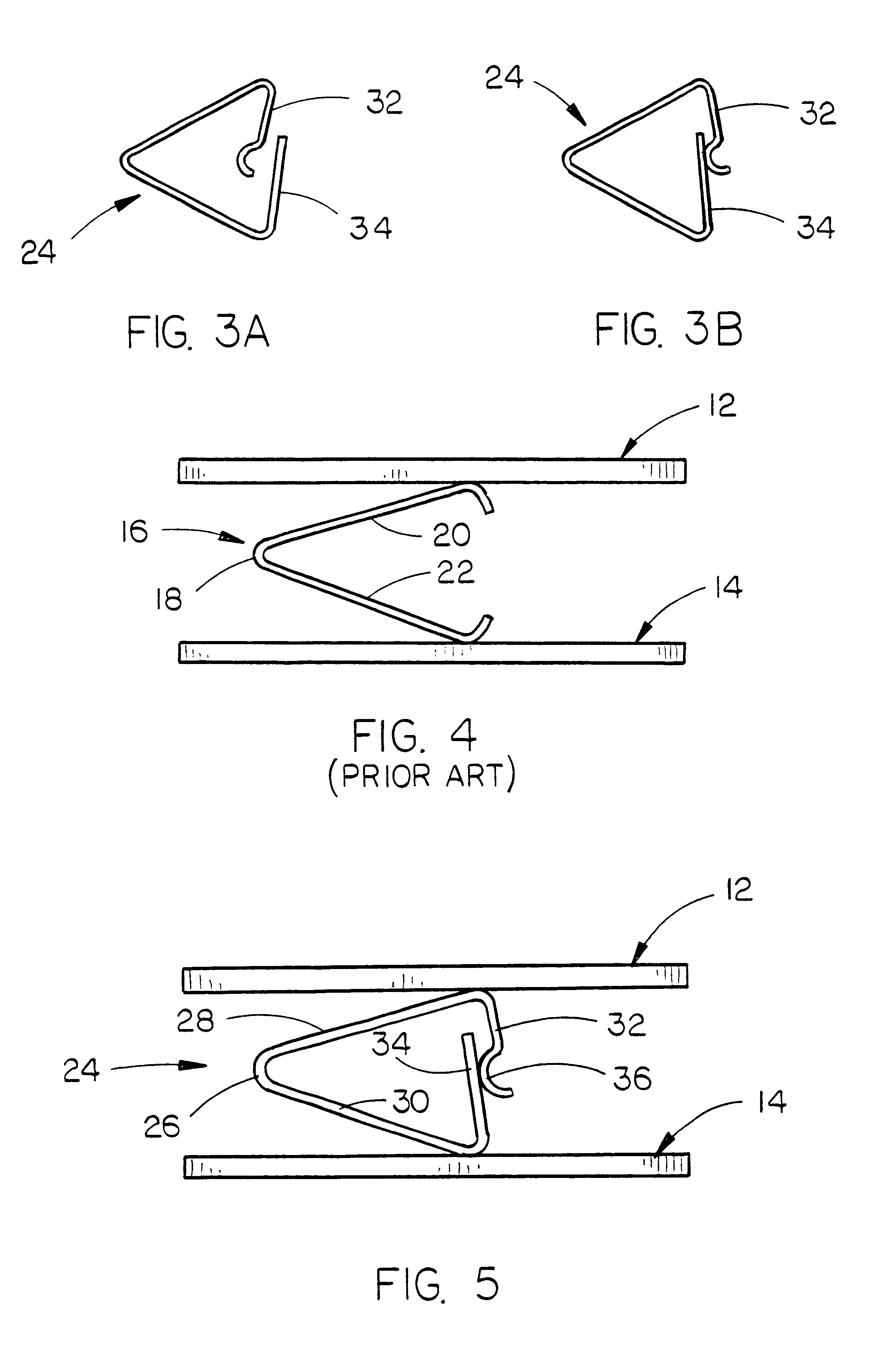
In the drawings, the numeral 10 refers to a conventional wireless communication device such as a cell phone having an internal antenna such as a planar inverted F antenna (PIFA) and a printed circuit board (PCB). In FIG. 4, the numeral 12 refers to a PIFA while the numeral 14 refers to a PCB. FIG. 4 illustrates a prior art switch contact which is generally referred to by the reference numeral 16. As seen in FIG. 4, the spring contact 16 includes a base portion 18 and leg portions 20 and 22, with the leg portions being in electrical contact with the PIFA 12 and the PCB 14, respectively. Inasmuch as the spring portion of the contact 16 is not enclosed, inductance is present. In most cases, the additional inductance causes the electrical size of the PIFA to be smaller to compensate for the inductance. Smaller electrical size in general means the gain will be lower.

The spring contact of this invention is referred to generally by the reference numeral 24 and includes a base portion 26 ha...


PUM


Abstract

A switch contact for a wireless communication device is disclosed which is comprised of a generally U-shaped spring contact positioned between a printed circuit board and a planar inverted F antenna in a compressed state for electrically connecting the printed circuit board to a feed point on the planar inverted F antenna. The leg portions of the spring contact are provided with spring extensions which are overlapped and which are biased towards one another.

Description

1. Field of the InventionThis invention relates to internal antennas for hand-held mobile telephones and wireless communication devices. More particularly, the present invention relates to a switch contact for connecting a planar inverted F antenna in the device to a printed circuit board therein.2. Description of the Related ArtInternal antennas for wireless communication devices are becoming more popular due to their ease of integration into the housing of the device, lower cost, and smaller profile. A popular internal antenna is the planar inverted F antenna (PIFA). A major difficulty encountered in mass production of a PIFA is the method used to inexpensively provide a connection between the signal on the printed circuit board (PCB) to the feed point on the PIFA. The simplest method is to insert spring contacts that apply pressure between the PCB and the PIFA. The proper amount of pressure is crucial for making a consistent, reliable electrical connection.Spring contacts of the ...

Claims


Application Information

Patent Timeline
Patent Type & Authority Patents(United States)
IPC IPC(8): H01Q1/24H01Q9/04H04B1/38
CPCH01Q1/243H01Q9/0421H04B1/3827
Inventor WINTER, JAMES BLAKE
Owner CENTURION WIRELESS TECH INC
Why Eureka
Try Eureka