
USB device that provides power that is different from power prescribed in the USB standard

a technology of usb devices and power supplies, applied in the direction of measuring devices, power supplies for data processing, instruments, etc., can solve the problems of increasing the cost of the device-side device, the inability of the measure to supply sufficient electric power to such a device, and the increase of the device, so as to achieve the effect of reducing the cos

Inactive Publication Date: 2007-01-02
FUJIFILM BUSINESS INNOVATION CORP
View PDF4 Cites 78 Cited by
  • Summary
  • Abstract
  • Description
  • Claims
  • Application Information

AI Technical Summary

Benefits of technology

[0012]Accordingly, an object of the present invention is to provide a USB device which is capable of supplying electric power in excess of 5V and 500 mA as prescribed by the USB interface standards to the device-side device by using only the general USB interface, with a minimal increase of cost.

Problems solved by technology

If another power source is installed to the device-side device in addition to the power source for the host-side device, the cost of the device-side device is much increased.
Installation of some power sources in one device, as in an assembling type device, leads to increase of the device, and is unacceptable since those will excessively occupy the limited inner space of the device.
The measure is incapable of supplying sufficient electric power to such a device that needs electric power which exceeds the standard electric power of 5V and 500 mA.
Thus, the USB interface alone is incapable of supplying electric power to the device-side device which consumes electric power in excess of the standard USB power supplying ability and the device-side device customized to have specific power source specifications.

Method used


Image

  • USB device that provides power that is different from power prescribed in the USB standard
  • USB device that provides power that is different from power prescribed in the USB standard
  • USB device that provides power that is different from power prescribed in the USB standard

Examples


Embodiment Construction

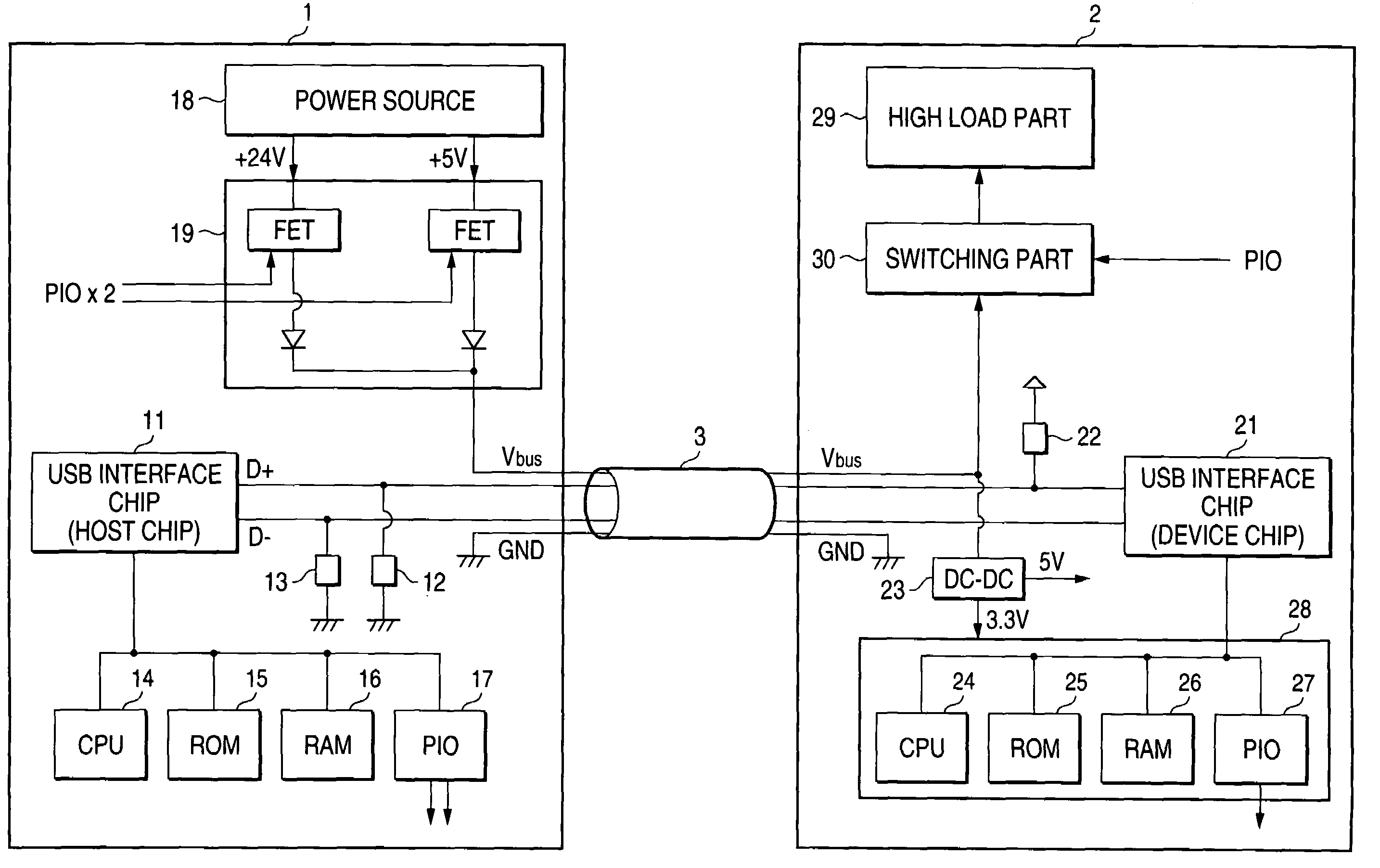
[0023]FIG. 1 is a block diagram showing an example of a system including a host-side USB device and a device-side USB device, which form an embodiment of the present invention. In the figure, reference numeral 1 is a host-side device; 2 is a device-side device; 3 is a cable; 11 and 21 are USB interface chips; 12, 13 and 22 are resistors; 14 and 24 are CPUs; 15 and 25 are ROMs; 16 and 26 are RAMs; 17 and 27 are PIOs; 18 is a power source; 19 is a voltage selector; 23 is a DC-DC converter; 28 is a low load part; 29 is a high load part; and 30 is a switching part. The host-side device 1 and the device-side device 2 are interconnected by the cable 3 and through the USB interface.

[0024]The host-side device 1 includes the USB interface chip 11, resistors 12 and 13, CPU 14, ROM 15, RAM 16, PIO (peripheral I / O) 17, power source 18 and voltage selector 19. The USB interface chip 11 communicates with the device-side device 2 through data lines D+ and D−. The resistors 12 and 13 are inserted b...


PUM


Abstract

A USB device for performing communications with a second device through a USB interface while supplying electric power to the second device through a power-source supplying line in the USB interface. The USB device includes a communication unit for communicating with the second device, a power source capable of outputting electric power of a voltage being different from a standard power voltage prescribed in the standards of the USB interface. The power source supplies the electric power to the second device through the power-source supplying line. The second device includes a low load unit and a high load unit The power source supplies the electric power having a power voltage higher than the standard power voltage to the high load unit through the power-source supplying line.

Description

BACKGROUND OF THE INVENTION[0001]1. Field of the Invention[0002]The present invention relates to USB devices which perform communications through a USB interface.[0003]2. Background Art[0004]Recently, the interface as specified by the USB standard has widely been used. FIGS. 3A and 3B are explanatory diagrams for roughly explaining an electrical connection when devices are connected by use of a USB interface. In the figure, reference numeral 31 is a host-side device; 32 is a host-side interface chip; 33 to 34 are resistors; 35 is a cable; 36 is a device-side device; and a 37 is a device-side interface chip. The USB is a serial interface of four core wires, and the host-side device 31 is connected to the device-side device 36 by a four core-wire cable 35. The four core wires are a power-source supplying line (Vbus), a ground line (CND), and two data lines (D+ and D−).[0005]The data lines are connected to the host-side interface chip 32 in the host-side device-31 and the device-side i...

Claims


Application Information

Patent Timeline
IPC IPC(8): G06F1/26G06F3/00
CPCG06F1/266G06F2213/0042
Inventor TAKAHASHI, HIROTASUGITA, HIROSHISONOBE, KENICHIEDOGAWA, KAZUYAKANEKO, TOMOKAZUHOSHINO, TSUTOMU
Owner FUJIFILM BUSINESS INNOVATION CORP
Learn More