
Portable toilet advertisement display system

a technology for displaying systems and portable toilets, which is applied in the direction of identification means, instruments, boards, etc., can solve the problems of system limitations in their ability to enhance aesthetics, detract from the aesthetic appeal of the environment, and general unattractive so as to enhance the appearance of portable toilets

Inactive Publication Date: 2007-01-09
ADDINK JOHN W
View PDF7 Cites 9 Cited by
  • Summary
  • Abstract
  • Description
  • Claims
  • Application Information

AI Technical Summary

Benefits of technology

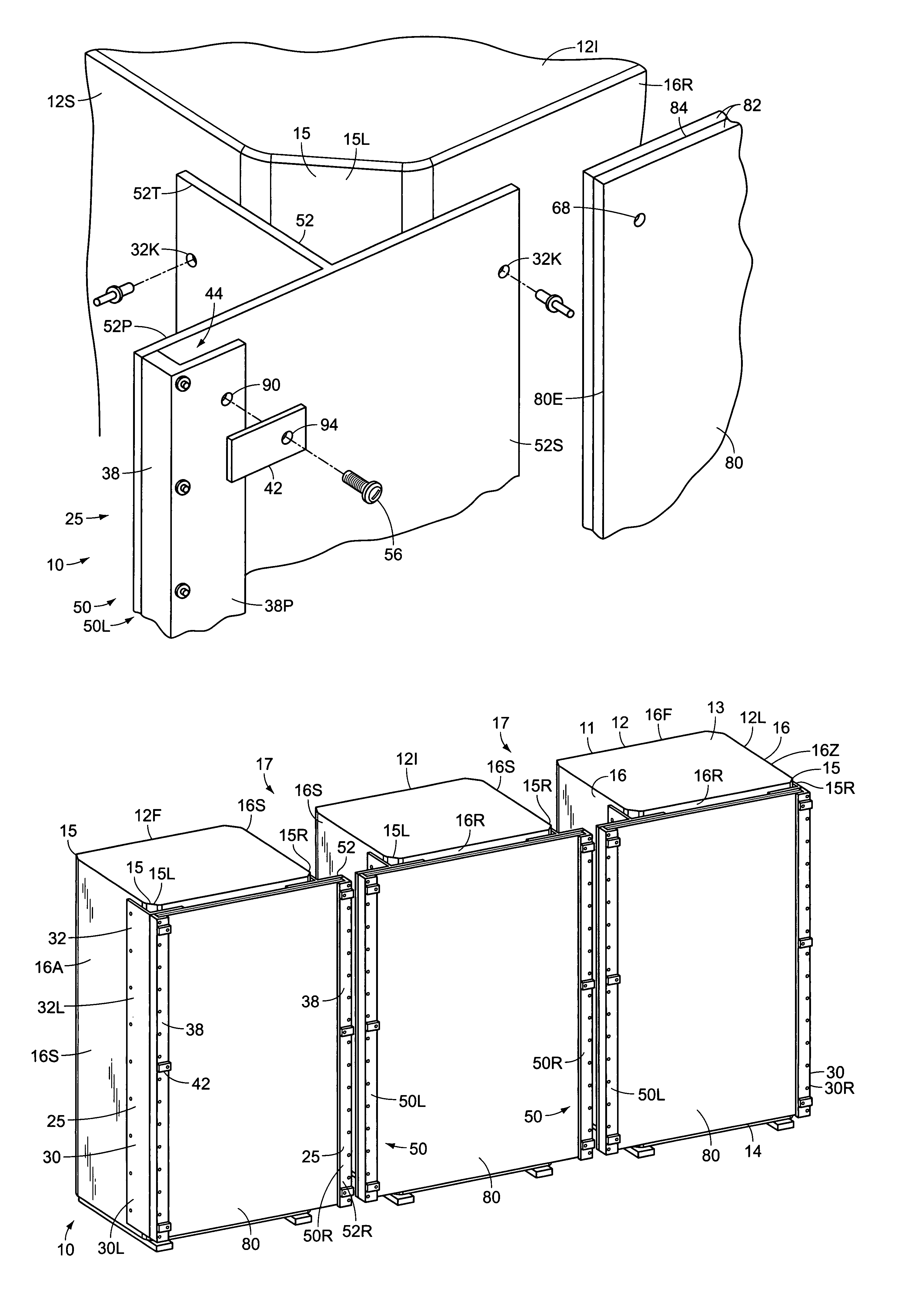
[0007]It is an object of the invention to provide a portable toilet advertisement display system which enhances the appearance of a portable toilet housing. Accordingly, the present invention allows one or more panel assemblies to be attached to a portable toilet housing. The panels can bear an advertising message or simply a decorative image, and thereby enhances the appearance of the portable toilet housing.
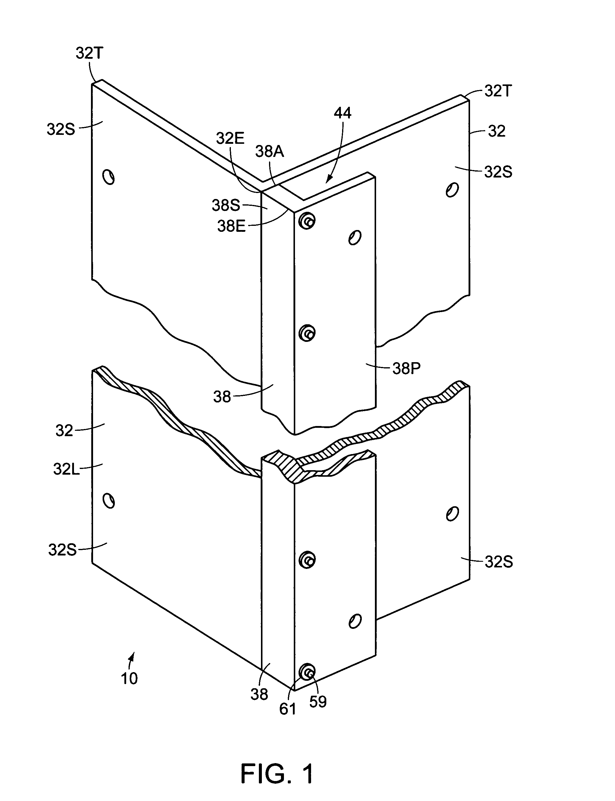
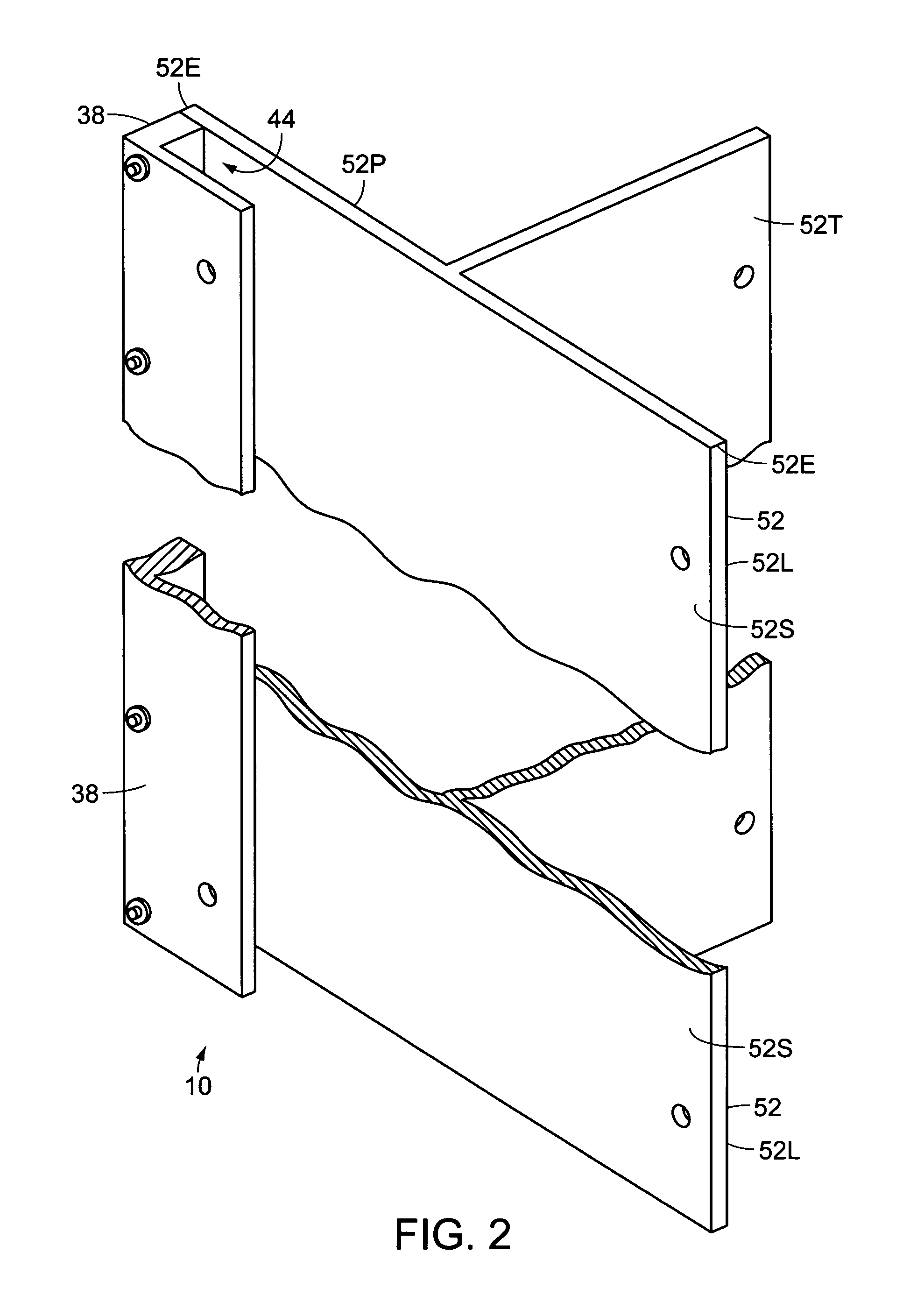
[0010]It is a further object of the invention to provide an advertisement display system that is attractive and highly visible. Accordingly, the brackets are preferably made of clear acrylic so as to minimize obscuring the edges of each advertising panel so that they together provide a continuous appearance.

Problems solved by technology

While portable toilets provide transitory restroom facilities to large numbers of people without the expense and commitment required to install water pipes and drainage pipes required for “fixed toilets”, they have a number of disadvantages.
In particular, portable toilets are generally visually unattractive, and detract from the aesthetic appeal of the environment in which they are situated.
However, these systems are limited in their ability to enhance the aesthetic appeal of a plurality of portable toilets arranged in a side-to-side array, having a gap between the individual toilets, and are useless for obscuring the gap between the toilets.

Method used


Image

  • Portable toilet advertisement display system
  • Portable toilet advertisement display system
  • Portable toilet advertisement display system

Examples


Embodiment Construction

[0021]FIG. 7 illustrates an advertisement display system 10 being used in conjunction with a plurality of existing portable toilets 11 having housings 12 arranged in a side-to-side array. The advertisement display system 10 comprises a plurality of different types of bracket assemblies 25, and a plurality of substantially rectangular advertising panel assemblies 80. The substantially rectangular toilet housings 12 each have an arcuate roof 13, a base 14, and four vertically extending walls 16, extending substantially between the base 14 and roof 13. The walls 16 include two side walls 16S, a rear wall 16R, and a front wall 16F. The front wall 16F has a door which selectively opens in order to allow a user to enter the toilet 11. The housings 12 each have four curved corners 15, each positioned between two adjacent walls 16, each corner 15 extending substantially from the base 14 to the roof 13. The corners 15 include a left rear corner 15L and a right rear corner 15R, when viewed fr...


PUM


Abstract

An advertisement display system, for use with a plurality of existing portable toilets arranged side-to-side with a gap between the toilets, for providing a substantially continuous advertising presentation. The system comprises a plurality of bracket assemblies each of which are selectively vertically attached along a corner of the toilet, and a plurality of substantially rectangular advertising panel assemblies which are selectively inserted between adjacent pairs of the bracket assemblies. The bracket assemblies include a plurality of intermediary bracket assemblies which are selectively mounted to the corners of the intermediary toilets in the series. A projecting portion of the intermediary bracket assembly extends beyond the side of the toilet to which it is attached. Accordingly, the advertising panel inserted into a vertical channel within the projecting portion also extends into the gap, thereby allowing the advertising display system to appear to be a single, continuous advertising panel.

Description

BACKGROUND OF THE INVENTION[0001]1. Field of the Invention[0002]The invention generally relates to a portable toilet advertisement display system, and in particular it relates to a portable toilet advertisement display system for use in conjunction with a plurality of existing portable toilets arranged in a side-to-side array, for allowing the toilets to be used to provide a substantially continuous advertising presentation.[0003]2. Description of the Related Art[0004]Portable toilets are frequently used during outdoor events, particularly ones which draw sizable numbers of people, such as concerts, plays, and sporting events. While portable toilets provide transitory restroom facilities to large numbers of people without the expense and commitment required to install water pipes and drainage pipes required for “fixed toilets”, they have a number of disadvantages. In particular, portable toilets are generally visually unattractive, and detract from the aesthetic appeal of the enviro...

Claims


Application Information

Patent Timeline
IPC IPC(8): G09F15/00A47K11/02
CPCG09F15/00
Inventor WIERINGA, LAWRENCE
Owner ADDINK JOHN W
Learn More