Snowboard binding with suspension heel loop

Inactive Publication Date: 2007-01-09
K 2 CORP
View PDF21 Cites 14 Cited by
  • Summary
  • Abstract
  • Description
  • Claims
  • Application Information

AI Technical Summary

Benefits of technology

[0006]In accordance with aspects of the present invention, a frame of a binding apparatus having a toe end and a heel end for securing an athletic shoe to a glideboard is provided. The frame includes a base section that is adapted for attachment to the glideboard and has medial and lateral heel end extensions and a bottom surface for supporting the shoe. The frame also includes an upper section having medial and lateral side members and a heel support member interconnecting the medial and lateral side members. The medial and lateral side members are pivotally connected to the base section such that the heel support member is movable between a first position and a second position. The frame further includes a first compressible device that engages against the upper section and the base section. The first compressible device controls the movement of the heel support member between the first and second position, while dampening vibration and absorbing forces applied thereto.
[0007]In accordance with another aspect of the present invention, a frame of a binding apparatus for securing a boot to a glideboard is provided. The frame includes a substantially rigid base section having toe and heel ends and medial and lateral sides. The base section also includes a bottom surface for supporting the boot, and a heel end extension upwardly extending from each of the medial and lateral sides of the base section. Each heel end extension forms an opening that is substantially coaxial to the other. The frame also includes an upper section having two spaced-apart fork members pivotally connected to the toe end of the medial and lateral sides of the base section at coaxial pivot connections. The fork members extend rearwardly and interconnect to form a heel support member. Each fork member forms an opening correspondingly dimensioned and alignable with the openings of the heel end extensions. The upper section is movable about the pivot connections along a path of travel between a first position, wherein the respective openings in the heel end extensions and the fork members are in substantial alignment, and a second position, wherein the respective openings are not in alignment. The frame further includes first and second compressible members engaging each of the aligned openings of the respective upper section and the heel end extensions. The compressible members operate to control and dampen the movement of the upper section between the first and the second position.
[0008]In accordan

Problems solved by technology

However, both of these approaches have their disadvantages.
With respect to providing camber to the binding, this c

Method used


Image

  • Snowboard binding with suspension heel loop
  • Snowboard binding with suspension heel loop
  • Snowboard binding with suspension heel loop

Examples


Embodiment Construction

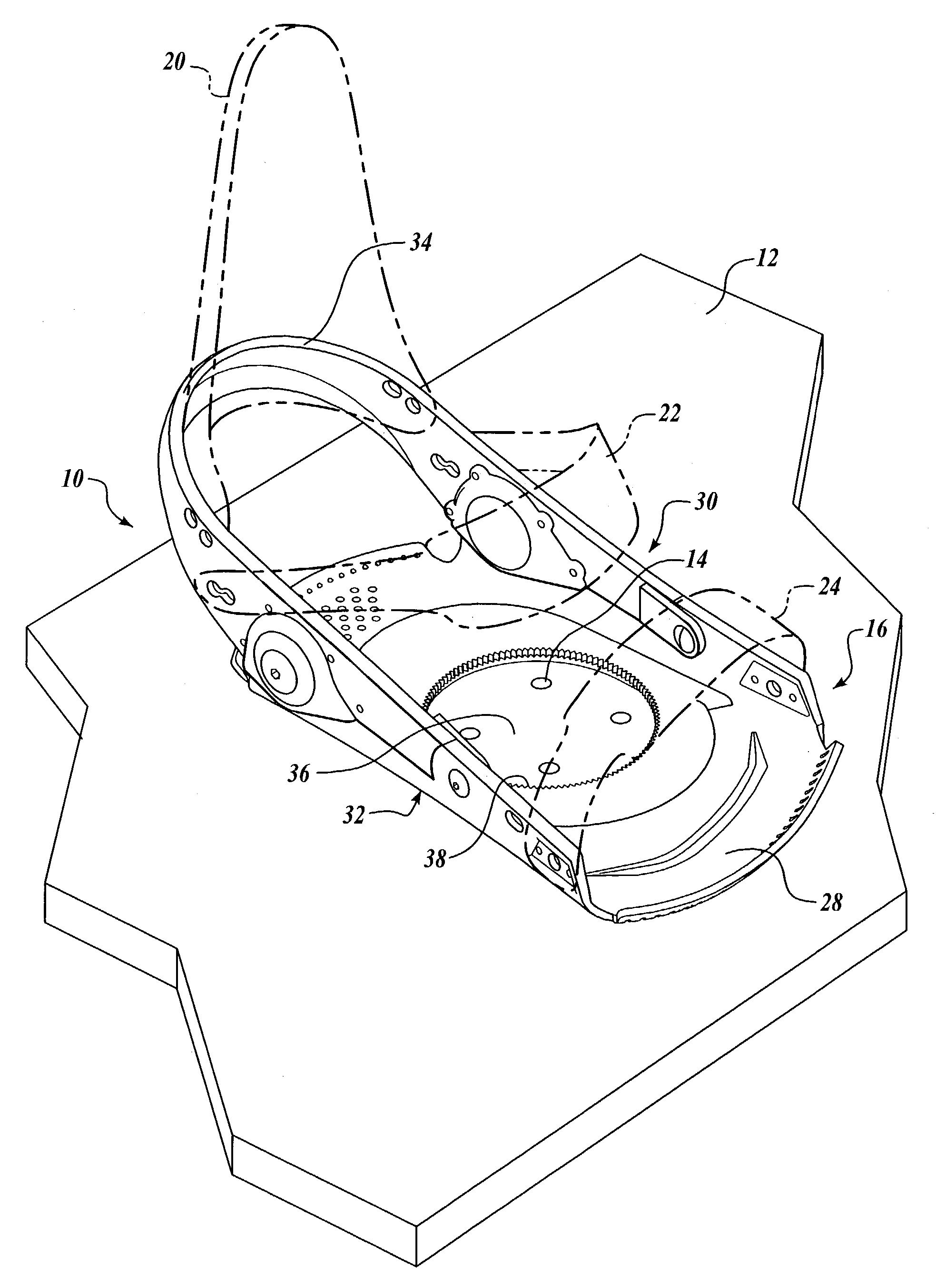
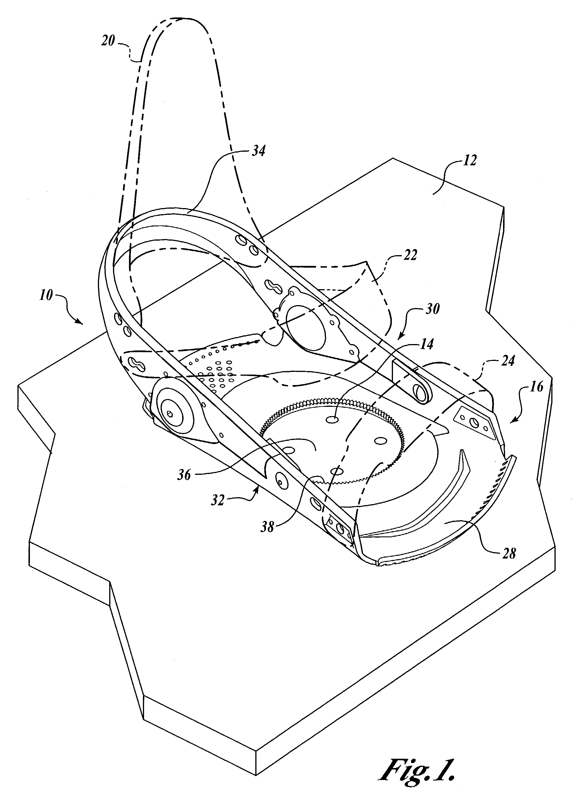
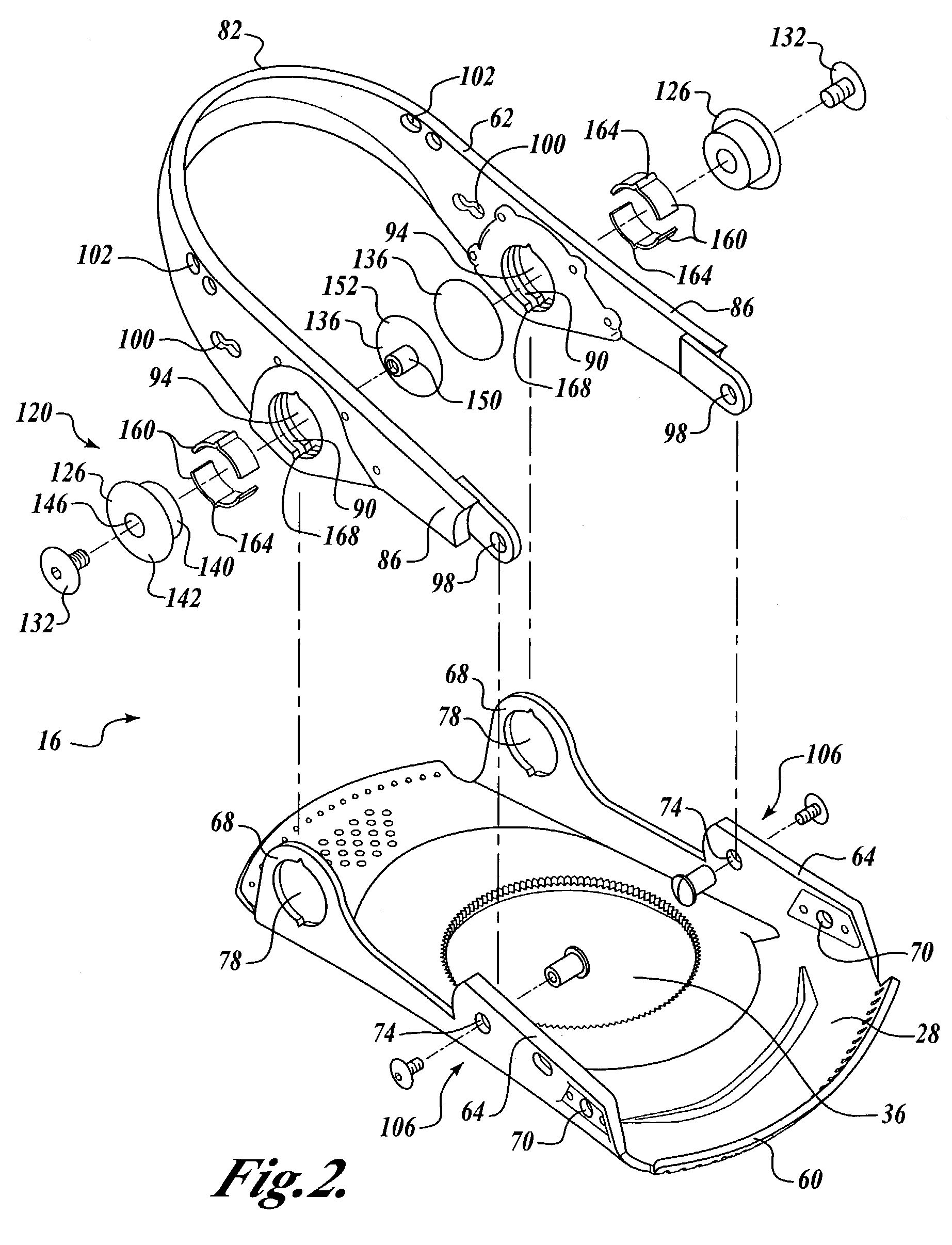
[0016]The present invention will now be described with reference to the accompanying drawings where like numerals correspond to like elements. The present invention is directed to a binding for a glideboard or other surface traversing apparatuses, including but not limited to snowboards, skis, wakeboards, and snowshoes, which provide movement between the athletic shoe or boot of the rider and the glideboard. Specifically, the present invention is directed to a snowboard binding having a heel loop that moves with respect to the binding base plate. More specifically, the present invention is directed to a binding having a suspension heel loop that flexes or moves in a controlled manner with respect to the base plate at the heel end of the binding. The binding of the present invention is designed to provide greater maneuvering and board control, and thus improves rider performance, while providing shock and vibration absorption capabilities for increasing the overall comfort of the bin...


PUM


Abstract

A binding includes a suspension heel loop formed by an upper member pivotally connected to the base of the binding frame. The heel loop flexes or moves in a controlled manner with respect to the binding base at the heel end of the binding. A binding having the suspension heel loop provides greater maneuvering and board control, and thus improves rider performance, while providing shock and vibration absorption capabilities for increasing the overall comfort of the binding during use.

Description

FIELD OF THE INVENTION[0001]The present invention relates generally to bindings for removably attaching an athletic boot to a surface traversing apparatus, such as a snowboard, and more particularly, to heel loop suspension systems for snowboard bindings.BACKGROUND OF THE INVENTION[0002]Snowboarding has been practiced for many years, and has grown in popularity in recent years, establishing itself as a popular winter activity rivaling downhill skiing. Typically, a rider wears snowboarding boots that are firmly secured to the snowboard so that the rider can control the speed and direction of the snowboard as the rider traverses a snow-covered hill. The snowboarder's boots are secured to the snowboard by a binding system that has one of a variety of overall configurations depending on intended use and rider preferences. Some riders utilize a two-strap binding system, also referred to as a conventional binding system, which includes straps for releasably securing the rider's boot to th...

Claims


Application Information

Patent Timeline
IPC IPC(8): A63C9/00A63C10/04A63C10/18A63C10/24A63C10/26
CPCA63C10/26A63C10/24A63C10/04A63C10/18
Inventor DRAPER, ALEXANDER D.STEERE, NIGELHEINLE, KENNETH WAYNE
Owner K 2 CORP
Why Eureka
Try Eureka