
Exercising air footboard and buffer for air footboard

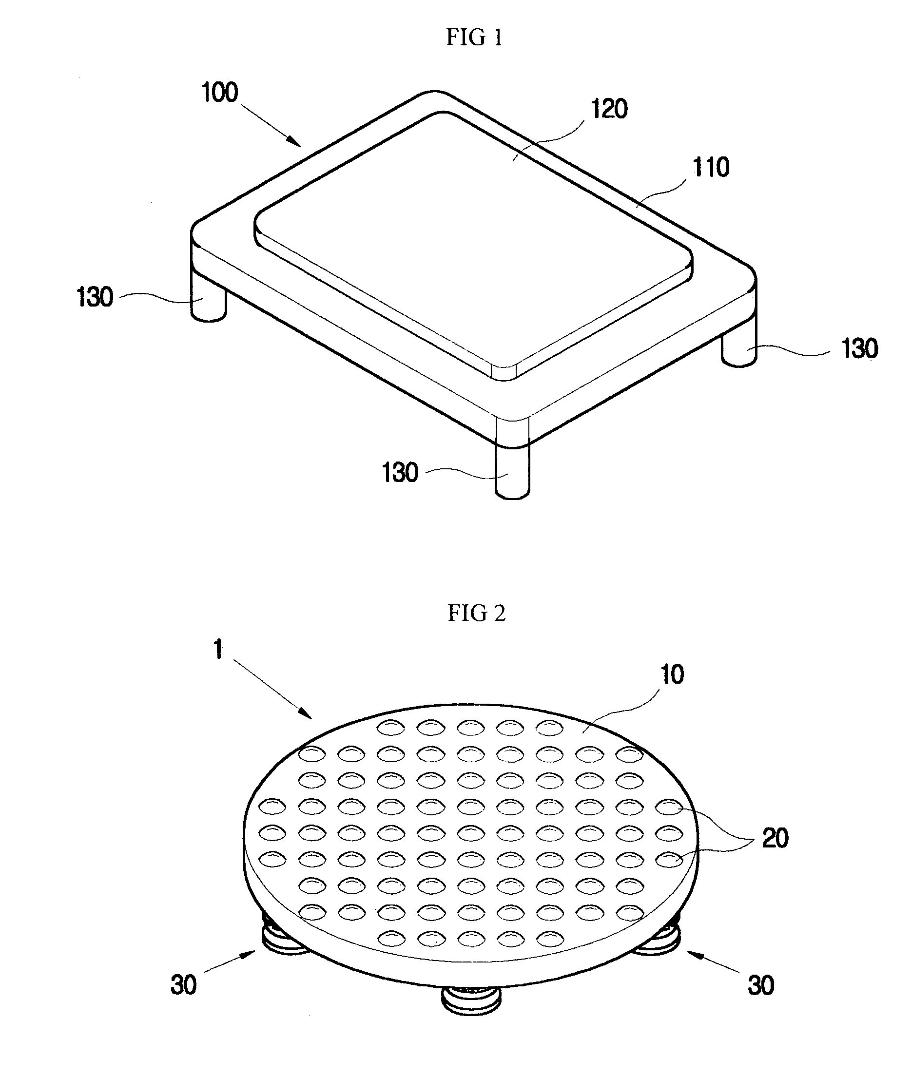
a technology of exercise step and air cushioning leg, which is applied in the direction of trampolines, gymnastics, stilts, etc., can solve the problems of insufficient cushioning capacity of exercise step 100, and inability to prevent shock transmission to user's knees, etc., to achieve excellent air cushioning effect, protect user's knees from injury, exercise in comfort and safety

Inactive Publication Date: 2007-01-09
EQUBIC PROD
View PDF9 Cites 29 Cited by
  • Summary
  • Abstract
  • Description
  • Claims
  • Application Information

AI Technical Summary

Benefits of technology

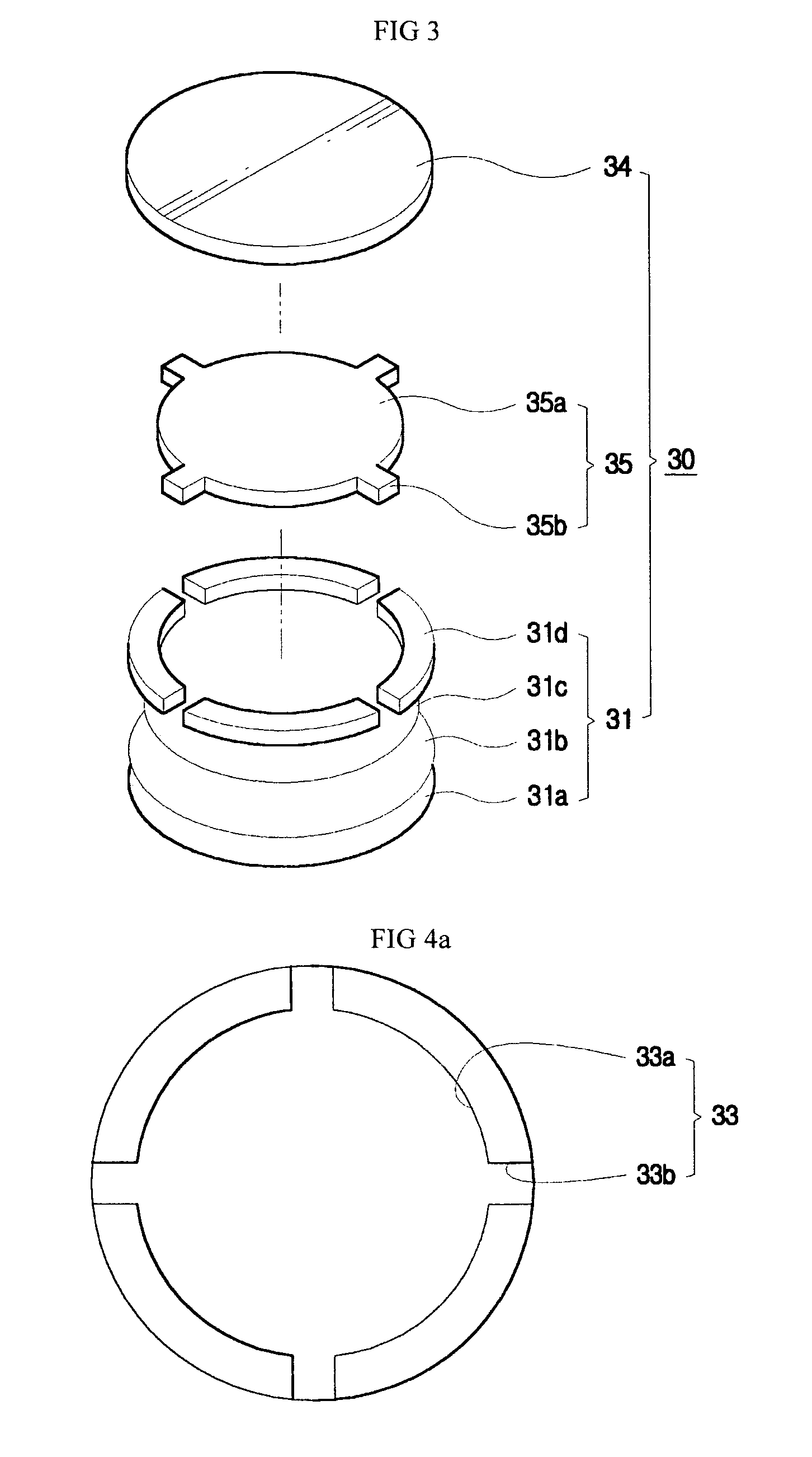
"The present invention provides an exercise step with air-cushioning legs that have an excellent air cushioning effect, protecting the user's knees from injury and allowing for comfortable and safe exercise. The design also minimizes noise and prevents deformation of the panel due to the user's load. Additionally, the invention allows the user to check the number of steps and exercise time while using the step. The air-cushioning leg includes a main body with a double- or more-layered structure and an air control unit functioning to discharge a part of cushioning air from the main body to the outside, when a load is applied to the support unit. The air-cushioning leg also includes a cover member covering the upper end of the main body in which the air control unit is seated."

Problems solved by technology

However, the conventional exercise step 100 has a problem that only the legs 130 are made of a cushioning material, such as polyurethane, so a cushioning capacity of the exercise step 100 is insufficient to prevent a shock from being transmitted to a user's knees.
Thus, the conventional exercise step 100 does not sufficiently prevent a shock from being transmitted to a user's knees and allow the user to exercise safely and comfortably.
Further, the conventional exercise step 100 has another problem that only the legs 130 have a cushioning capacity, so the foot contact plate 120 and the panel 110 may be undesirably deformed when the exercise step 100 is used for a lengthy period of time.
The conventional exercise step 100 has a further problem that the cushioning capacity of the legs 130 is not controlled, so a different exercise step must be purchased according to a user's weight.

Method used


Image

  • Exercising air footboard and buffer for air footboard
  • Exercising air footboard and buffer for air footboard
  • Exercising air footboard and buffer for air footboard

Examples


second embodiment

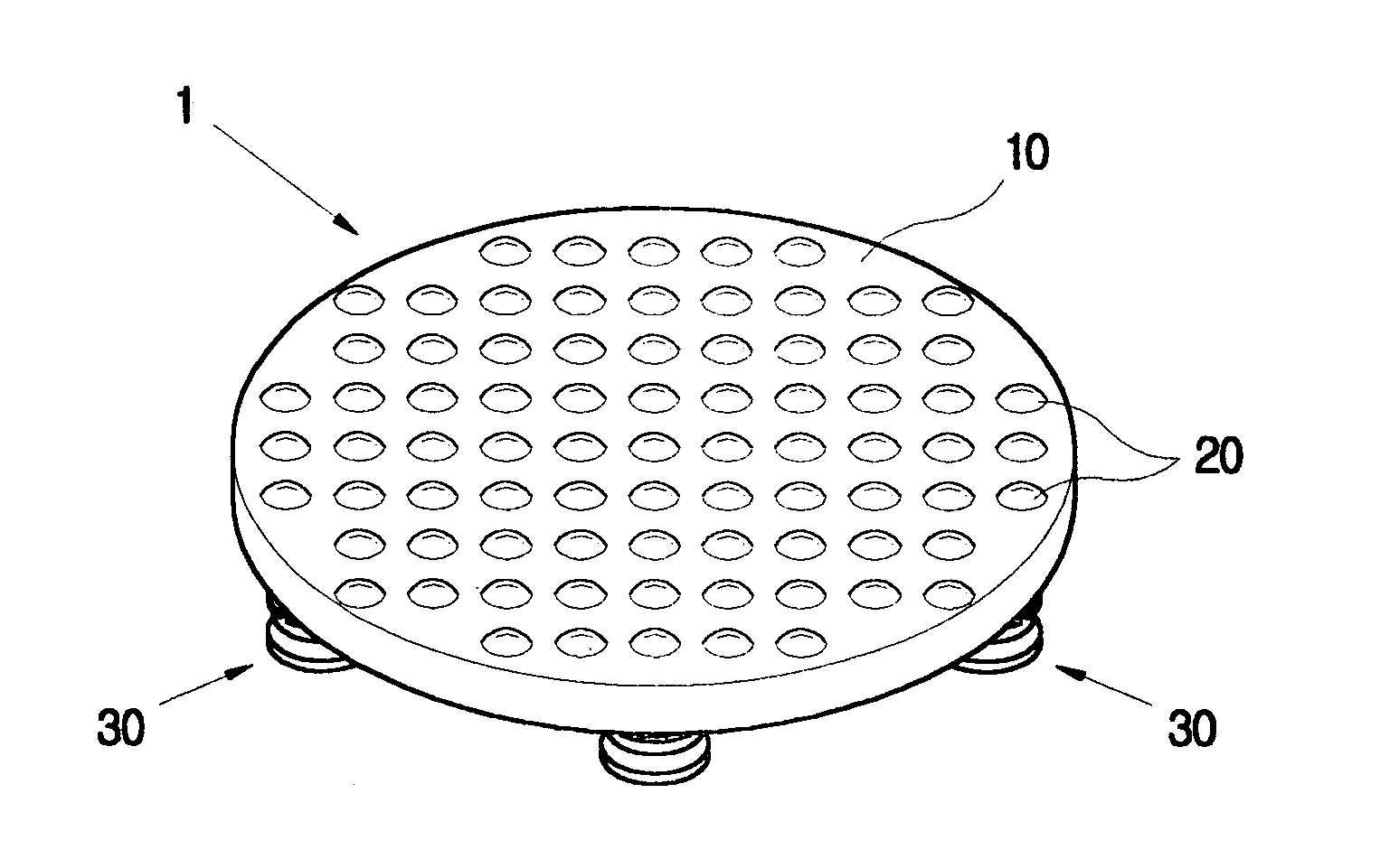
[0053]As shown in FIG. 6, an exercise step 1 according to the present invention includes a rectangular plate-shaped panel 10 and a plurality of air-cushioning legs 30. The air-cushioning legs 30 are mounted to four corners of the panel 10 under the panel 10. A rectangular foot contact plate 20 is provided on a top surface of the panel 10. The foot contact plate 20 is made of an elastic material, such as rubber, thus giving comfort to a user and having some cushioning effect.

[0054]The panel 10 is a kind of laminated compressed wood, and is fabricated by processing multi-layered sheets to which a synthetic resin is added, under high temperature and high pressure. Thus, the panel 10 is somewhat hard, and has excellent elasticity and elastic strain, so the panel 10 is not easily damaged or deformed.

[0055]A display unit 14 is provided at a predetermined portion of the panel 10. The display unit 14 is connected to a control unit (not shown), and displays at least one of the number of step...

third embodiment

[0068] shown in FIG. 9, a main body 40′ of each air-cushioning leg 30′ is designed such that two cover parts 42 and 43 are provided at an open lower part of the main body 40′. In this case, the two cover parts 42 and 43 partially overlap with each other to form an overlapping part. An adjusting bolt 44 is tightened into the overlapping part in such a way that the cover parts 42 and 43 are spaced apart from each other by a predetermined interval, thus controlling the amount of air which flows out of the main body 40′.

[0069]According to a fourth embodiment shown in FIG. 10, an air flow opening 45 is provided at a side of a main body 40″, and a sliding door 46 is mounted to the air flow opening 45 to control an opening ratio of the air flow opening 45. The main bodies 40′ and 40″ according to the third and fourth embodiments also have foot parts 32 at the bottom surfaces of the main bodies 40′ and 40″.

[0070]Although not shown in the drawings, several through holes having a predetermine...

fifth embodiment

[0071]Further, shown in FIG. 11a, a plurality of air flow holes 151a are bored through a cover part 151 which is provided at the upper portion of the main body 140. When a control part 152 is rotated, one or more air flow holes 151a are opened. Alternatively, the main body of each air-cushioning leg may be designed to have a structure shown in FIG. 11b. In FIG. 11b, the reference numerals designate components corresponding to those shown in FIG. 11a. The components similar to those shown in FIG. 11a are not described herein in detail.

[0072]According to the fifth and sixth embodiments of FIGS. 11a and 11b, the air flow holes 151a and 252a are provided at the upper portions of the main bodies 140 and 240, respectively. However, air flow holes may be formed as shown in FIG. 11c, to accomplish the same effect as the air flow holes 151a and 252a of FIGS. 11a and 11b. That is, according to a seventh embodiment of FIG. 11c, a plurality of air flow holes 353a are provided in the bottom sur...


PUM


Abstract

Disclosed herein is an exercise step and an air-cushioning leg for the exercise step. The exercise step (1) includes a plate-shaped panel (10), and air-cushioning legs (30). Each of the air-cushioning legs is provided under the panel to support the panel, and absorbs a load applied to the panel by air cushioning effect. The exercise step has a high air cushioning effect, thus protecting a user's knees from injury, allowing the user to exercise in comfort and safety, and minimizing noise generated during a cushioning operation. Further, the exercise step prevents the panel from being deformed due to a load applied to the panel.

Description

TECHNICAL FIELD[0001]The present invention relates, in general, to an exercise step and an air-cushioning leg for the exercise step and, more particularly, to an exercise step which is designed to have an excellent air cushioning effect, thus protecting a user's knees from injury and allowing the user to exercise in comfort and safety, and which is designed to minimize noise generated during a cushioning operation.BACKGROUND ART[0002]FIG. 1 is a perspective view of a conventional exercise step. As shown in the drawing, the conventional exercise step 100 includes a rectangular panel 110, and four legs 130. The legs 130 are provided at four corners of the panel 110 under the panel 110, and are made of elastic materials. A foot contact plate 120 is provided at a top surface of the panel 110. Actually, a user's feet are in contact with the foot contact plate 120 of the panel 110.[0003]When one desires to exercise using the exercise step 100, the exercise step 100 having such a construct...

Claims


Application Information

Patent Timeline
Patent Type & Authority Patents(United States)
IPC IPC(8): A63B22/04A63B5/16A63B6/00A63B23/04A63B24/00
CPCA63B23/0458A63B2225/62A63B2220/17A63B2071/0063
Inventor PARK, HEE-SUN
Owner EQUBIC PROD
Learn More