Articulated equipment position control system and method

a technology of position control and articulating equipment, applied in the direction of position fixation, underwater vessels, non-deflectable wheel steering, etc., can solve the problems of particularly challenging guiding of articulated agricultural equipment, and achieve the effect of simple configuration

Active Publication Date: 2007-01-09
AGJUNCTION
View PDF17 Cites 150 Cited by
  • Summary
  • Abstract
  • Description
  • Claims
  • Application Information

AI Technical Summary

Problems solved by technology

However, guiding articulated agricultural equipment is particularly challenging because crop damage can be caused by either the motive or the working component, or both.

Method used


Image

  • Articulated equipment position control system and method
  • Articulated equipment position control system and method
  • Articulated equipment position control system and method

Examples


first modified embodiment

VII. First Modified Embodiment Dual-Receiver System 102

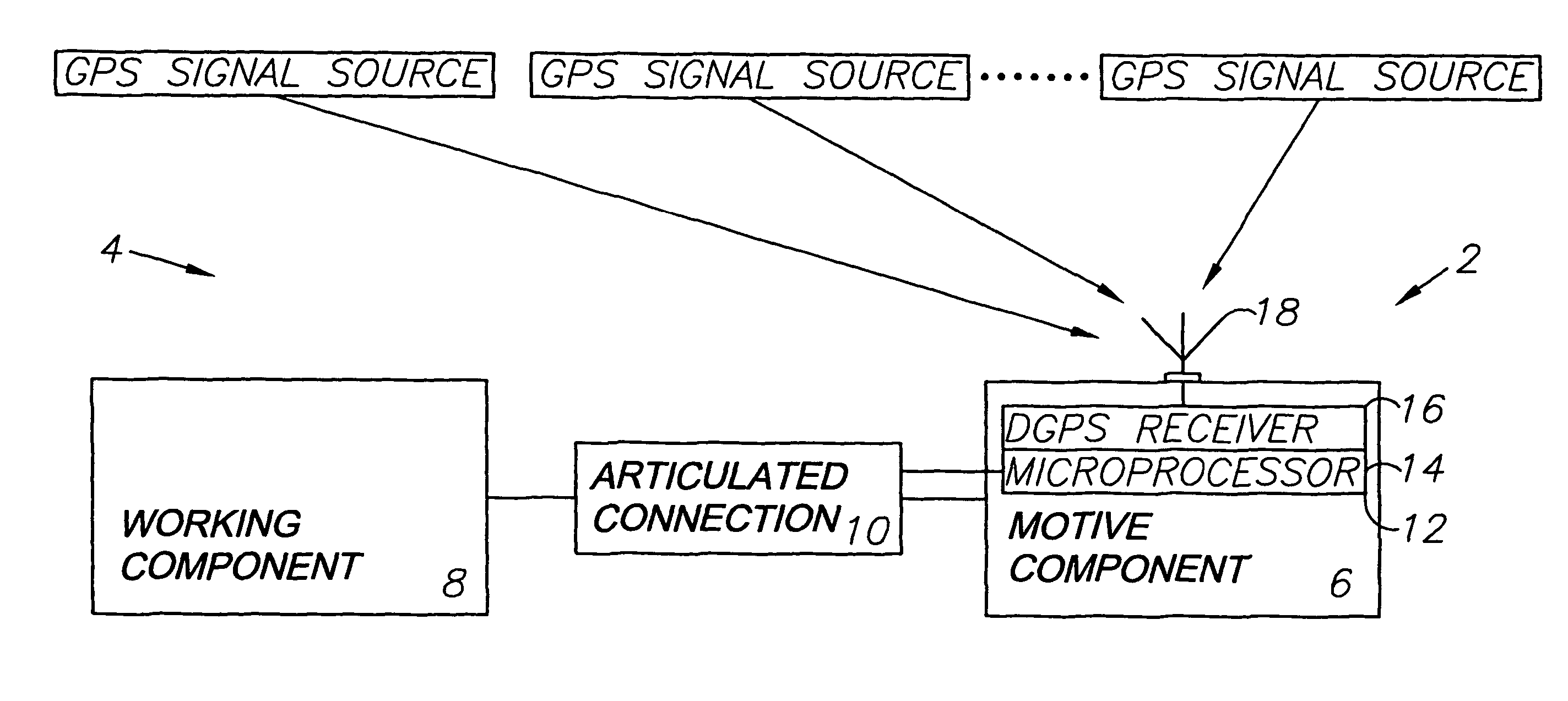
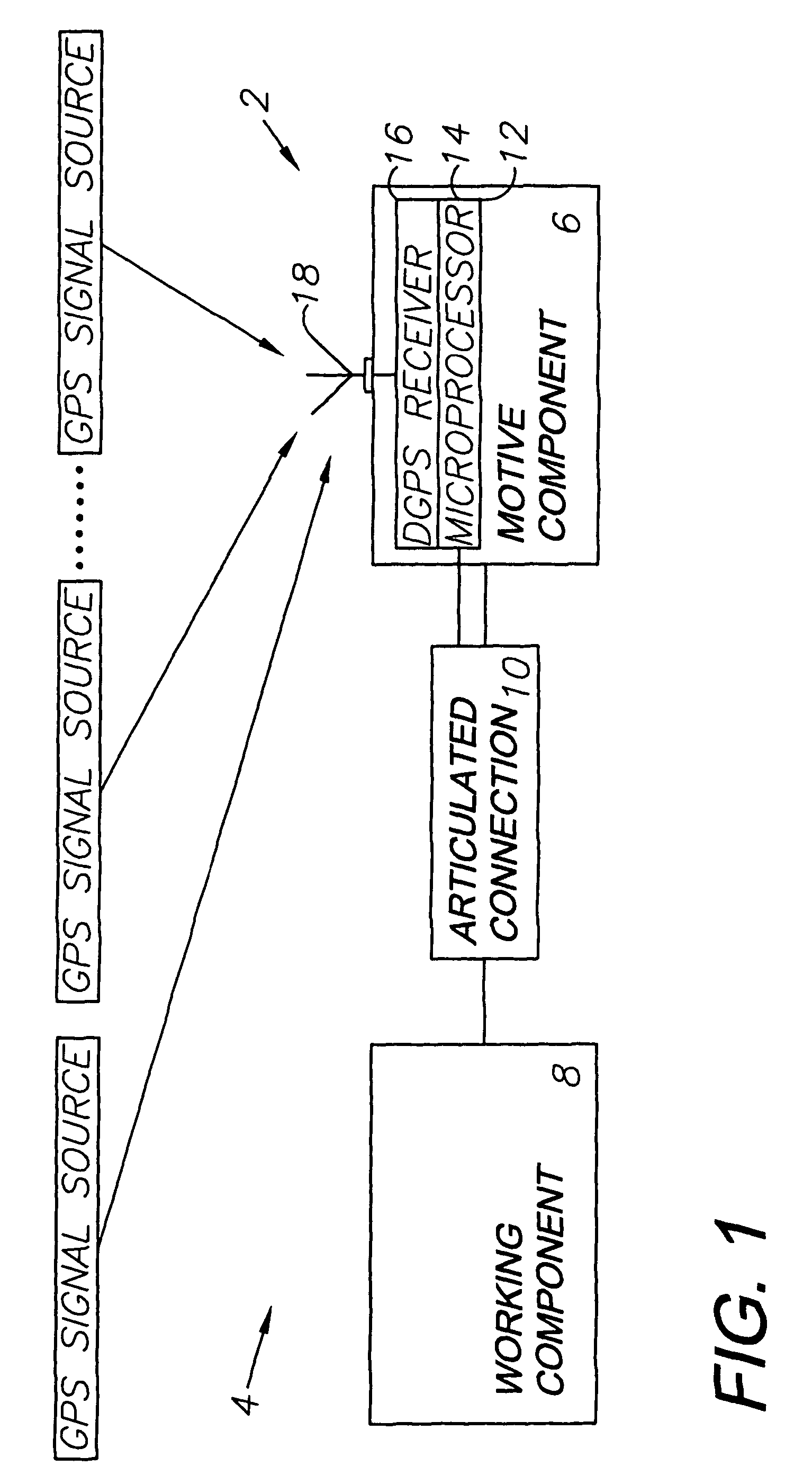
[0049]FIG. 11 shows articulated equipment 104 with a position control system 102 comprising a first modified embodiment of the present invention. The system 102 includes first and second DGPS receivers 110, 112 mounted on motive and working components 106, 108 respectively. This configuration can be used for automatic steering of the motive component 6 using the first DGPS receiver 110 and fine positioning of the working component (implement) 8 using the second DGPS receiver 112.

[0050]It is to be understood that the invention can be embodied in various forms, and is not to be limited to the examples discussed above. Other components can be utilized. For example, the working component can comprise a sprayer with spray booms connected to a vehicle and adapted to be raised and lowered in response to GPS position data.


PUM


Abstract

An articulated equipment position control system and method are provided for equipment consisting of motive and working components. The components are connected by an articulated connector, such as a pivotal hitch. GPS-derived positional data is utilized for power-articulating the hitch to maintain the working component, such as an implement, on a predetermined course. Operator-induced course deviations can thus be corrected. The working component can also be positioned to follow the course of the motive component. The system includes a microprocessor control subsystem, which interfaces with a steering guidance system.

Description

CROSS-REFERENCE TO RELATED APPLICATION[0001]This application claims the benefit of U.S. provisional application No. 60 / 432,719, filed Dec. 11, 2002, which is incorporated herein by reference.BACKGROUND OF THE INVENTION[0002]1. Field of the Invention[0003]The present invention relates generally to articulated equipment position control, and particularly to a system and method for DGPS-based positioning of an operative piece of equipment, such as a farm implement, which is pulled, pushed or carried by a motive piece of equipment, such as a tractor, by manipulation of a power-articulated connection therebetween.[0004]2. Description of the Related Art[0005]Various equipment systems include articulated components. For example, a common configuration involves a “motive” component, which supplies the motive force for pulling, pushing or carrying a “working” component through an articulated connection located therebetween. For example, tractors serve as motive components in agricultural and...

Claims


Application Information

Patent Timeline
Patent Type & Authority Patents(United States)
IPC IPC(8): G06F19/00G01S19/14A01B69/00A01B79/00G01S5/14G01S19/23
CPCA01B69/004A01B79/005G01S19/41G01S19/14
Inventor MCCLURE, JOHN A.HEINIGER, RICHARD W.TIMM, JOHN T. E.FUNK, KENT D.WONG, RICHARD B.
Owner AGJUNCTION
Why Eureka
Try Eureka