
Engine control device

a control device and engine technology, applied in the direction of electric control, machines/engines, ignition safety means, etc., can solve the problem of increasing the amount of intake air

Active Publication Date: 2007-01-16
MITSUBISHI ELECTRIC CORP +1
View PDF8 Cites 22 Cited by
  • Summary
  • Abstract
  • Description
  • Claims
  • Application Information

AI Technical Summary

Benefits of technology

The patent describes an engine control system that can adjust the amount of air supplied to the engine and the timing of ignition to prevent abnormal acceleration or engine stopping. The system detects abnormalities in the throttle valve and adjusts the ignition timing accordingly to prevent damage to the engine. The system also includes a limp-home mechanism that maintains the throttle valve in a neutral position in case of an abnormality. The technical effect of this system is to ensure safe operation of the engine and prevent damage to the engine in case of an abnormality.

Problems solved by technology

Therefore, if the engine speed switches to the speed in the abnormal condition from a speed in a low speed range, for example an idle condition, it is likely that the intake air amount increases to accelerate the boat, or that the fuel injection amount cannot follow the increase of the intake air amount and the engine stops.

Method used


Image

  • Engine control device
  • Engine control device
  • Engine control device

Examples


Embodiment Construction

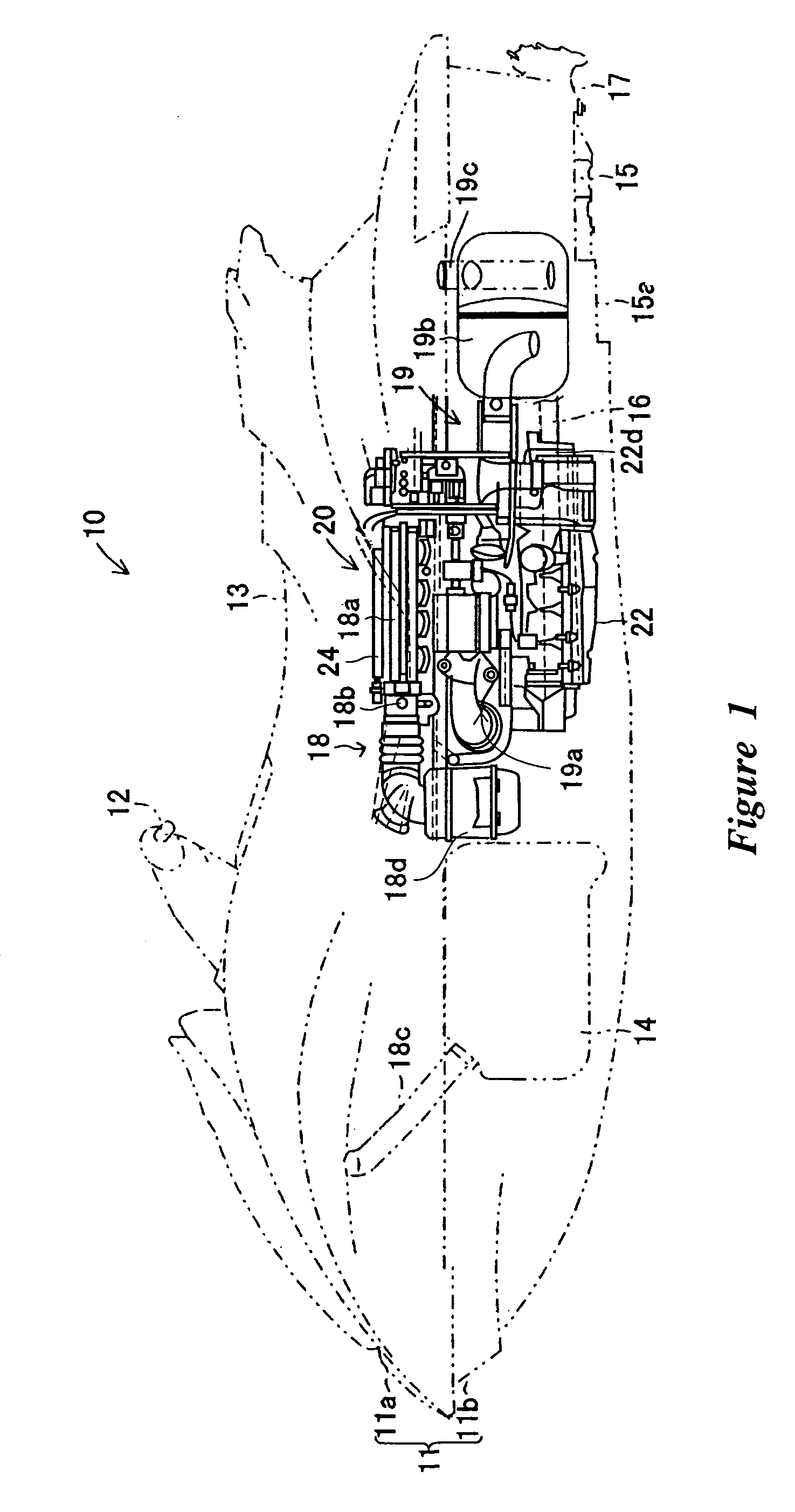
[0030]An embodiment is described below with reference to the drawings. FIG. 1 shows a personal water-jet propulsion watercraft 10 with an engine control device 20. The embodiments disclosed herein are described in the context of a personal watercraft because these embodiments have particular utility in this context. However, the embodiments and inventions herein can also be applied to other marine vessels, such as and small jet boats, as well as other vehicles.

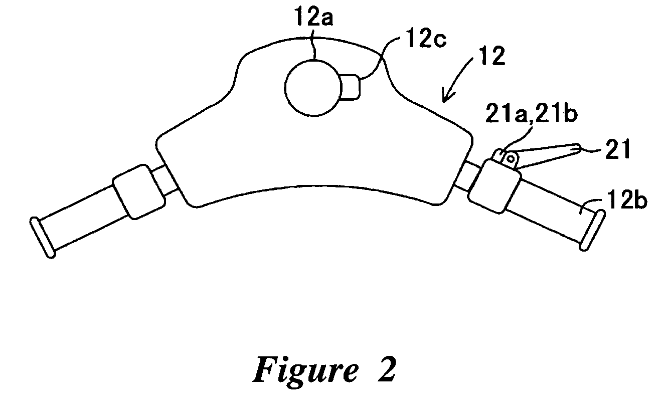
[0031]With reference to FIG. 1, in the boat 10, a boat body 11 is formed of a deck 11a and a lower hull 11b. A steering handle 12 is provided in the upper part of the boat body 11 at a portion, forwardly of the center. A seat 13 is provided in the upper part of the boat body 11 at about the middle of the boat 10. The steering handle 12, also shown in FIG. 2, is mounted to the upper end of a steering shaft 12a provided in the boat body 11, for rotation about or with the steering shaft 12a.

[0032]With reference to FIG. 2, in the...


PUM


Abstract

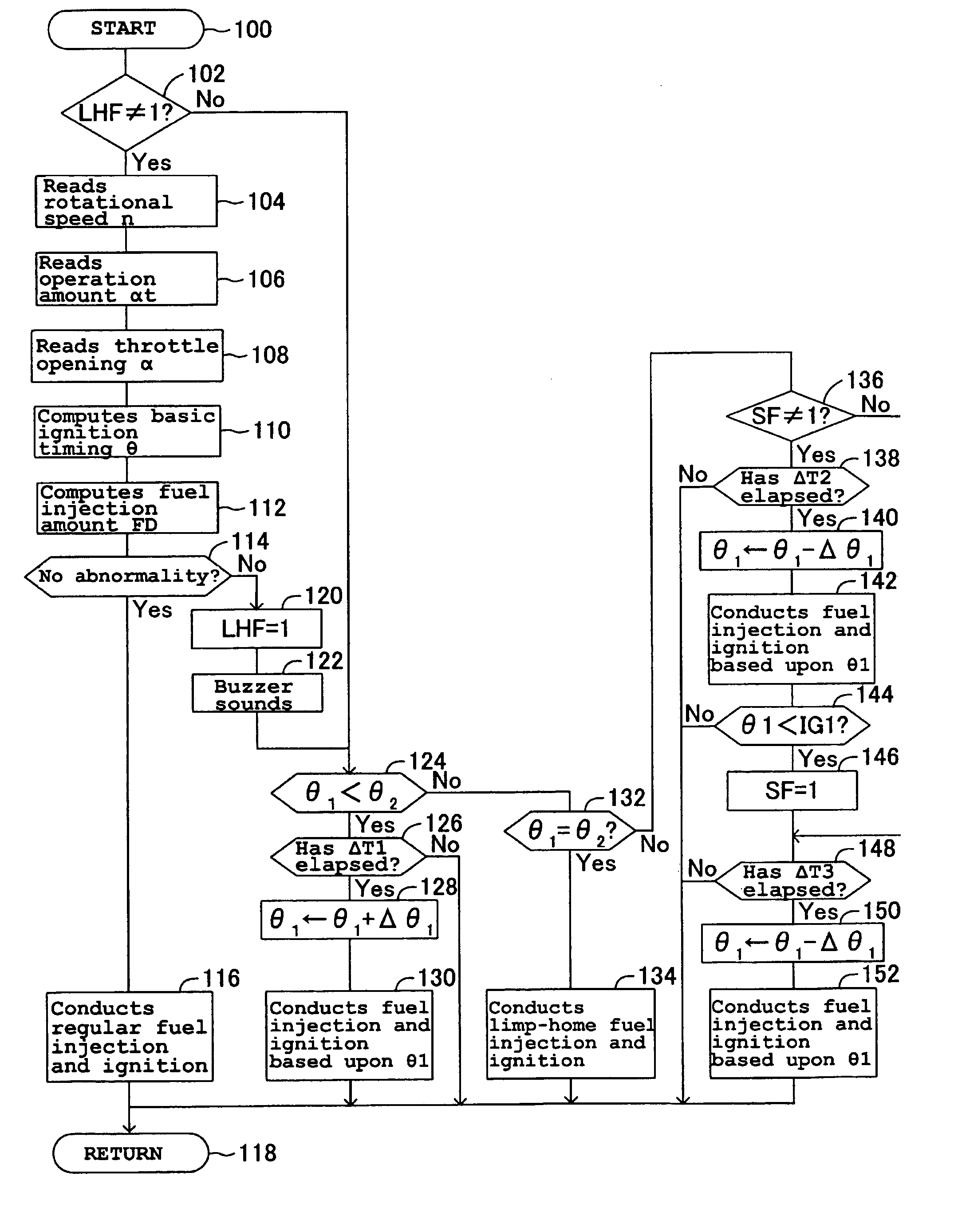
An engine control device can include a throttle valve for adjusting an amount of air supplied to an engine, operation amount detecting sensors for detecting an operation amount of a throttle lever, a motor for driving the throttle valve between open and closed positions according to detection values of the operation amount detecting sensor 21a or the like, and throttle opening detecting sensors for detecting an opening of the throttle valve is provided with a limp-home mechanism for keeping the throttle valve in a mechanically neutral position when an abnormality occurs. When the throttle valve is in the mechanically neutral position, an ignition timing control can be switched in a stepwise manner over a predetermined time period from a regular ignition timing control to a limp-home ignition timing control.

Description

PRIORITY INFORMATION[0001]This application is based on and claims priority under 35 U.S.C. §119 to Japanese Patent Application No. 2005-007470, filed on Jan. 14, 2005, the entire contents of which is hereby expressly incorporated by reference herein.BACKGROUND OF THE INVENTIONS [0002]1. Field of the Inventions[0003]The present inventions relate to an engine control device including modes for engine operation during malfunctions, and more specifically, during induction system malfunctions.[0004]2. Description of the Related Art[0005]Conventionally, for example in a small boat, an operation or displacement amount of an operating lever, also referred to as a “torque request device” or a “throttle lever”, by a boat operator is detected by an operation amount detecting sensor. In these types of watercraft an engine control device is typically used to control an electronically controlled throttle valve that adjusts an amount of air supplied to the engine. The throttle valve can be opened ...

Claims


Application Information

Patent Timeline
Patent Type & Authority Patents(United States)
IPC IPC(8): F02D11/10F02D11/00
CPCF02D9/1065F02D11/107F02P5/1502F02P11/02F02D2009/0277Y02T10/46F02D2041/227Y02T10/40
Inventor ISHIDA, YASUHIKOKINOSHITA, YOSHIMASA
Owner MITSUBISHI ELECTRIC CORP
Learn More