Damage resistant mailbox support structure

a support structure and mailbox technology, applied in the field of mounting and supporting structures, can solve the problems of less effective performance, no significant separation, and the support member itself is susceptible to damage to vehicles or equipment, so as to reduce the potential damage of the support structure, eliminate significant weight and mass, and reduce the effect of damage to the mailbox

Inactive Publication Date: 2007-01-16
DELINE RANDALL L +2
View PDF17 Cites 10 Cited by
  • Summary
  • Abstract
  • Description
  • Claims
  • Application Information

AI Technical Summary

Benefits of technology

[0011]The invention provides for support of a mailbox structure on an essentially horizontal axis, perpendicular to a vertical support structure, allowing the entire mailbox structure, and the opening in the front thereof, to extend roadward, away from the support structure, thus minimizing potential damage to the support structure, as an added benefit. The device is also constructed to allow it to move vertically or horizontally, or in some combination thereof, about the horizontal longitudinal axis of the mailbox structure itself, when struck from the top, bottom or side, or any angle in between.
[0012]The present invention combines support for the mailbox structure itself, extending from the mounting post, with the feature of a contained inherent biasing means also comprising the support member, eliminating significant weight and mass which would otherwise be added to the mailbox and structure. This also allows for the mailbox to be moved upon impact with less force, which, accordingly, results in less or no damage to the mailbox, or to vehicles, equipment or persons contacting it, when struck with like force.

Problems solved by technology

The disclosure of the Gould patent, however, suggests less effective performance when the mailbox structure is hit at an upward or downward angle; U.S. Pat. No. 3,658,284, to Hassl, discloses a yieldable support structure.
Further, Guthrie, like much of the prior art, does not provide a significant horizontal extension between the front of the mailbox and the support structure, which can be critical for avoiding vehicular contact or contact by road maintenance equipment in rural settings; U.S. Pat. No. 2,550,338, to J. B. Dunnigan, is another example of prior art which discloses a support for mailboxes or the like, again, provides a mailbox mounted on a rigid pivotal arm, which is returned to its original position by biasing means.
Further features and limitations of the prior art include, in several instances, a rigid rotatable support member, which support member itself is susceptible of damaging vehicles or equipment contacting the mailbox or the support structure.
Other limitations include the need for a separate biasing means, apart from the essential support bracket for the mailbox itself, and, very significantly, most of the prior art, without separate rigid rotatable support members, requires that the mailbox be mounted on the bottom of its enclosure structure, to the top of a support member or pole, thus eliminating any significant separation of the mailbox structure from the support pole and further exposing the support pole or member to additional potential damage from vehicles or road maintenance equipment, persons or the like.
Beyond referenced contact by vehicles and road maintenance equipment, particularly in rural area, vandalism, sometimes euphemistically described as “mailbox baseball,” is a severe problem, as well.
In such circumstances, vandals may strike the mailbox with rigid objects, from a passing vehicle, or on foot.

Method used


Image

  • Damage resistant mailbox support structure
  • Damage resistant mailbox support structure
  • Damage resistant mailbox support structure

Examples


Embodiment Construction

[0023]Throughout the following detailed description, like numerals are used to describe the same element of the present invention and the multiple figures thereof.

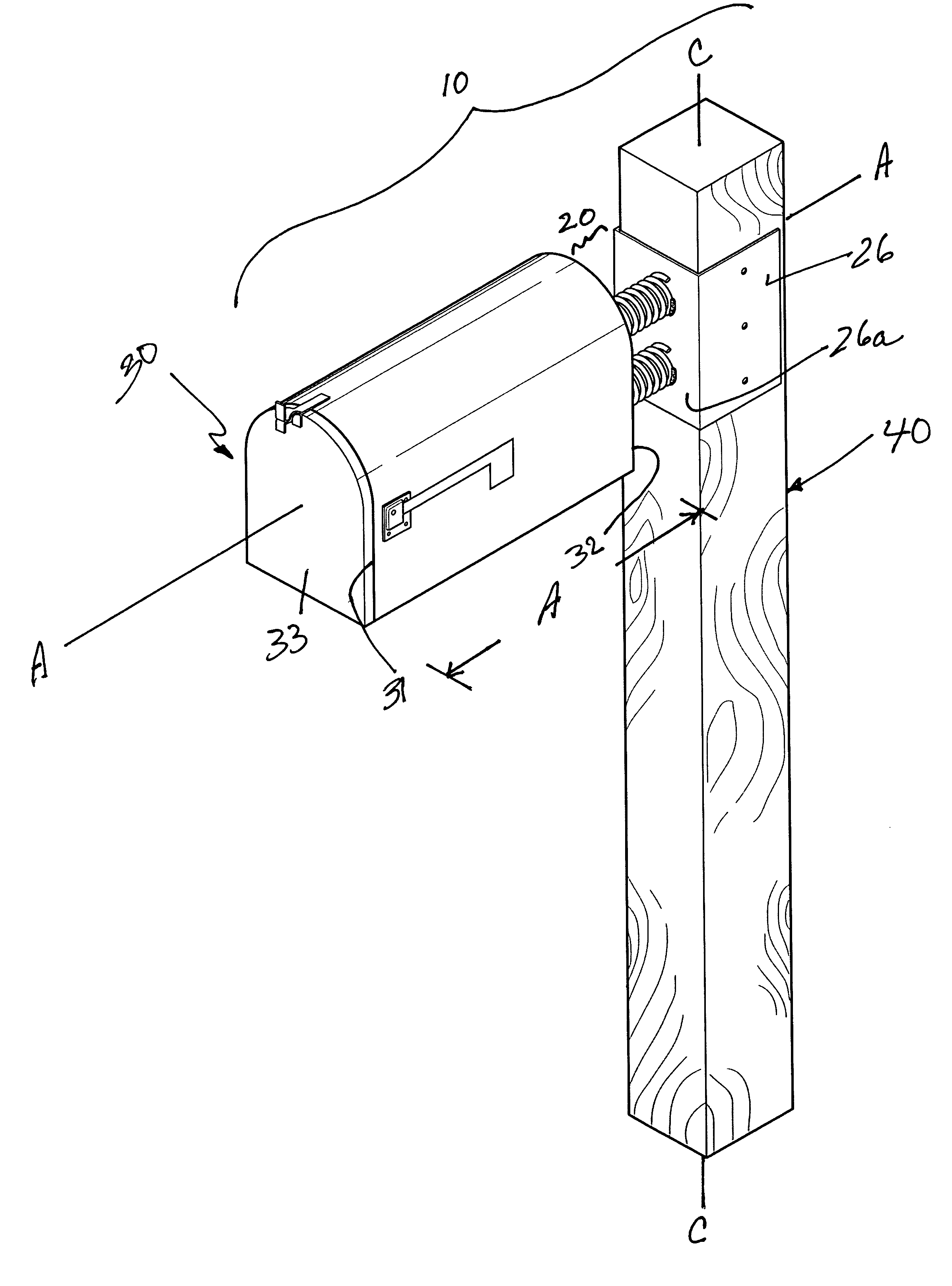
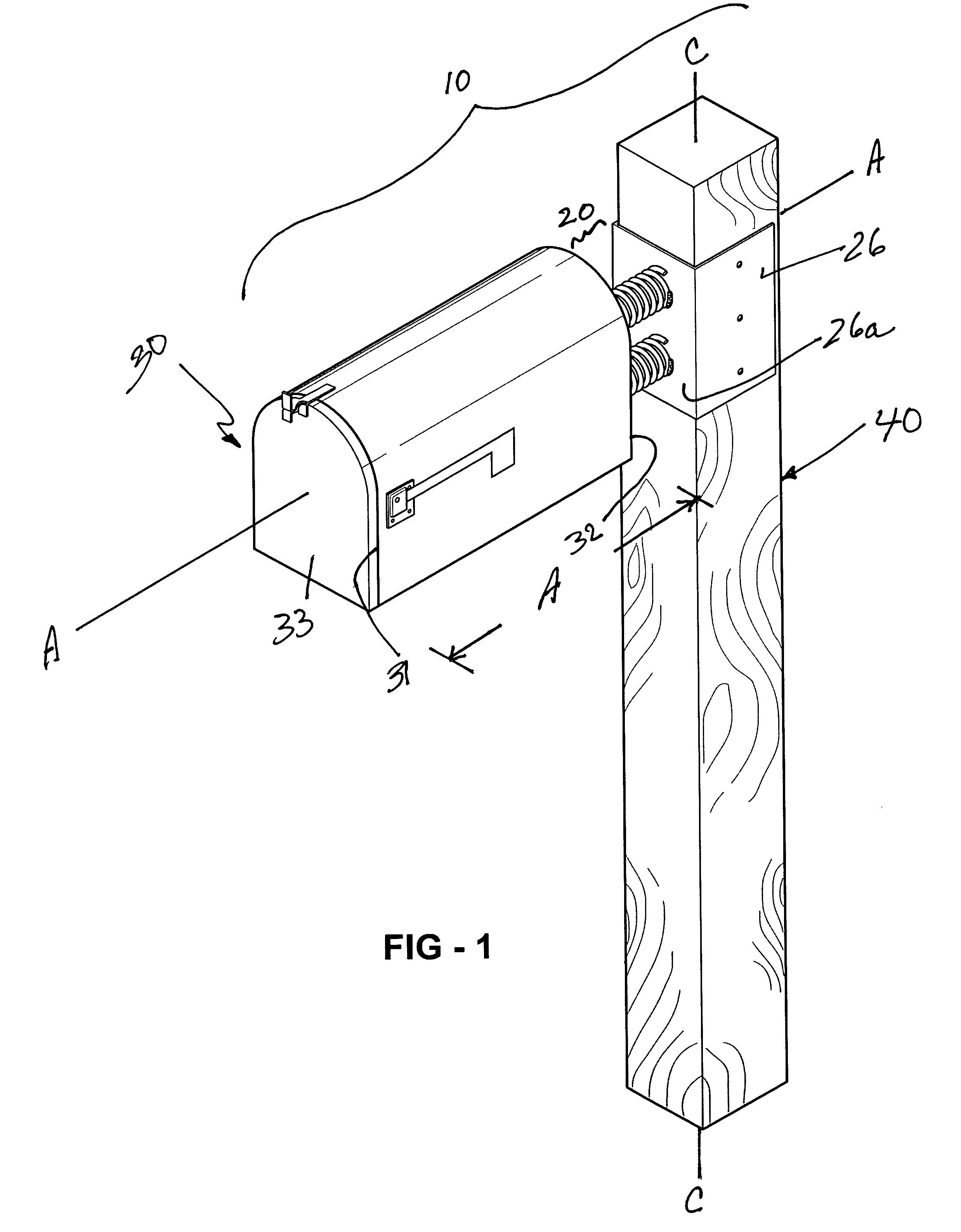
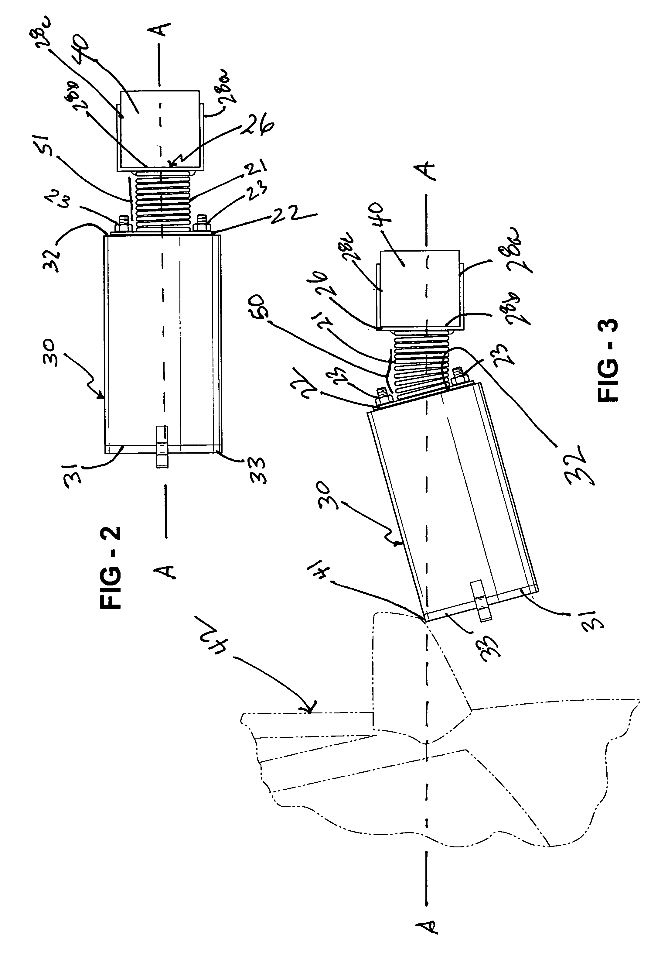
[0024]The invention, Damage Resistant Mailbox Support Structure, is a damage resistant mailbox support structure which allows movement of a standard mailbox enclosure, when struck by an outside force, both horizontally and vertically, and in combinations thereof, about the longitudinal, substantially horizontal axis of the mailbox structure, as normally mounted.

[0025]Broadly considered, the invention 10 consists of a support structure assembly 20 supporting a standard mailbox enclosure 30 from a supporting pole or structure 40.

[0026]The mailbox enclosure 30 is of standard construction in the industry and further has forward openable end 31 and a rearward closed end 32. End 31 is openable by means of a hinged door 33.

[0027]In standard installation, enclosure 30 is installed along a substantially horizontal axis A—A, along i...


PUM


Abstract

A damage resistant mailbox assembly to prevent damage to mailboxes and vehicles, persons or equipment which contact same. The mailbox is supported from an upright support post or structure by one or more expandable and bendable spring units. One end of each spring unit is attached to a plate which is in turn attached to the support post or structure. The other end of each spring unit is attached to the closed end of a standard mailbox enclosure. The device provides for movement of the mailbox when struck by external force, within a 360° radius about an axis substantially parallel to each support spring, with each spring biasing a return to the mailbox structure's original position.

Description

[0001]This application claims the benefit of Provisional Application No. 60 / 679,420, filed May 10, 2005.BACKGROUND OF THE INVENTION[0002]The instant invention, Damage Resistant Mailbox Support Structure, relates, generally, to a device to prevent damage to mailboxes and damage to vehicles, persons, or other equipment which may incidently contact a mailbox, in a standard rural roadside application. The present invention relates more particularly to the mountings and support structures for mailboxes, which, in the instant invention, improve upon the prior art in this field allowing the mailbox to move multidirectionally, and, optimally, in any direction within a 360° radius, about the longitudinal axis of the mailbox structure when the mailbox is struck by a person, a vehicle, road equipment, or any other object.[0003]The concept of providing a pivotable mailbox structure, or a support device for a mailbox, which allows the mailbox to move, in some respect, and with some biasing means...

Claims


Application Information

Patent Timeline
Patent Type & Authority Patents(United States)
IPC IPC(8): A47G29/12
CPCA47G29/1216
Inventor DELINE, RANDALL L.LUEDTKE, KERRYHARRIS, JAMES
Owner DELINE RANDALL L
Why Eureka
Try Eureka