Vehicle bumper beam having non-uniform cross sections

a bumper beam and cross section technology, applied in the direction of bumpers, vehicle components, vehicular safety arrangements, etc., can solve the problems of imposing limits on the dimensions of bumpers, damage to other parts of the vehicle, and more complex calculations, etc., to achieve high strength

Inactive Publication Date: 2007-01-16
F TECH R&D NORTH AMERICA
View PDF14 Cites 34 Cited by
  • Summary
  • Abstract
  • Description
  • Claims
  • Application Information

AI Technical Summary

Problems solved by technology

However, if the force is too great, excess energy will be transferred to the vehicle frame, resulting in damage thereto, and if the stroke is too great, there may be damage to portions of the vehicle other than the bumper.
For more complicated shapes, the calculations are more complex.
Furthermore, there will be limits imposed on the dimensions of the bumper, as it will be required to fit between the ends of the side rails and behind and under the vehicle fascia.
In addition, a vehicle manufacturer may set weight requirements and cost requirements for a bumper.
Therefore, when roll forming is used to produce a bumper, it typically results in a constant radius of curvature for the bumper as a whole.
Having such a constant radius of curvature and constant cross section imposes limitations on the design of the bumper.
As a result, roll formed bumpers do not always have the design flexibility needed to adjust to the performance requirements and / or layout requirements of modern motor vehicles.

Method used


Image

  • Vehicle bumper beam having non-uniform cross sections
  • Vehicle bumper beam having non-uniform cross sections
  • Vehicle bumper beam having non-uniform cross sections

Examples


Embodiment Construction

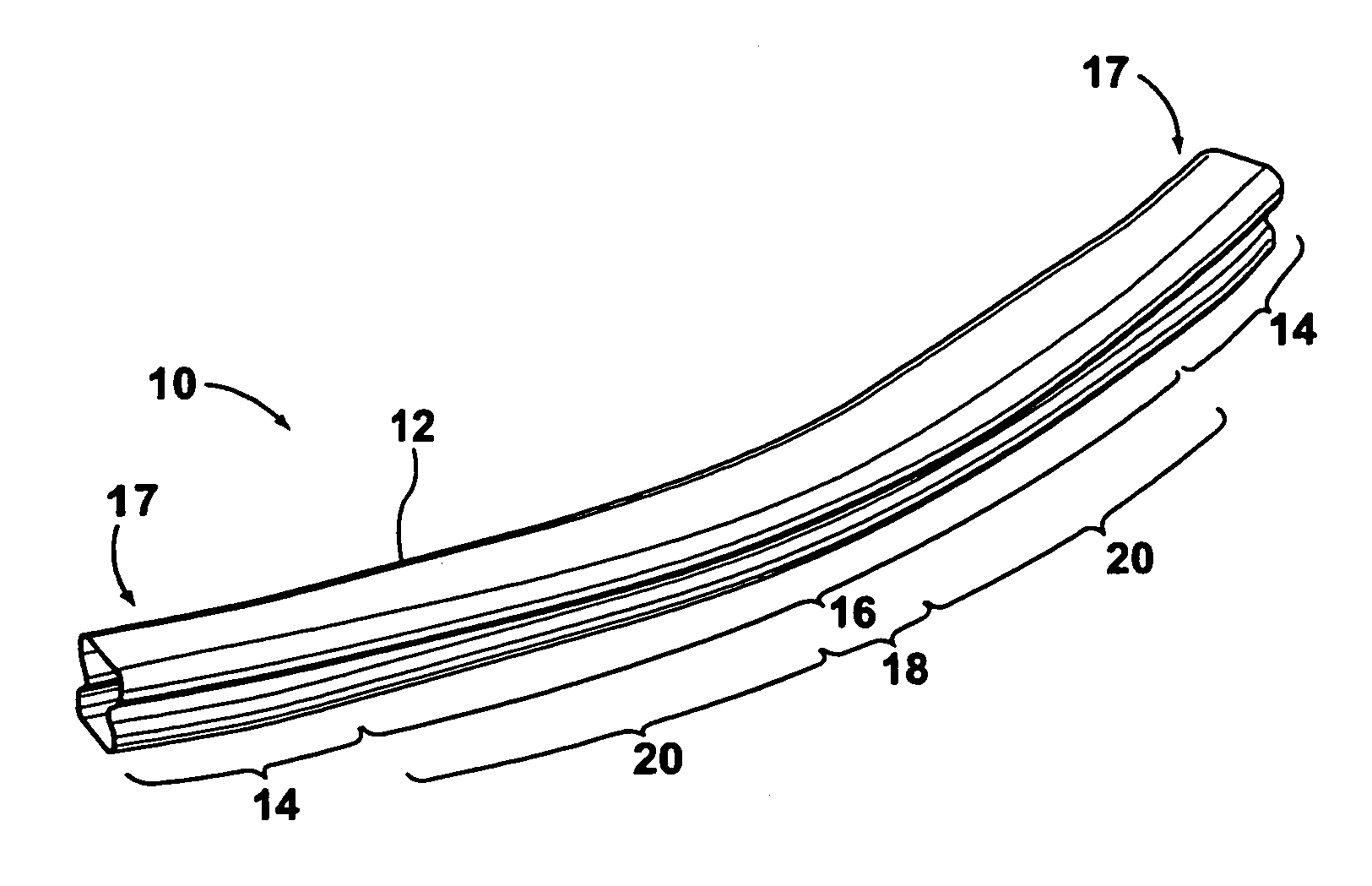
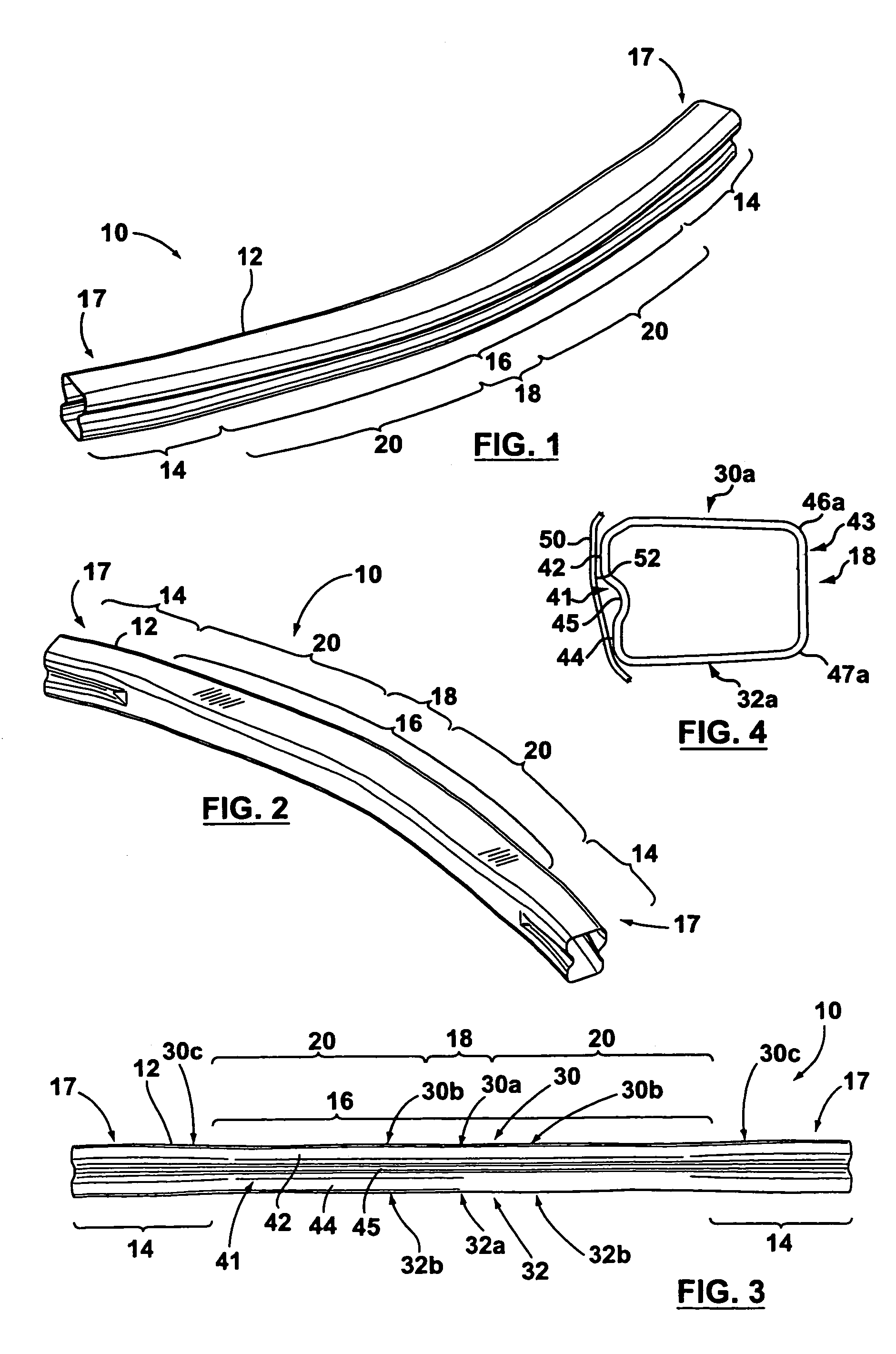
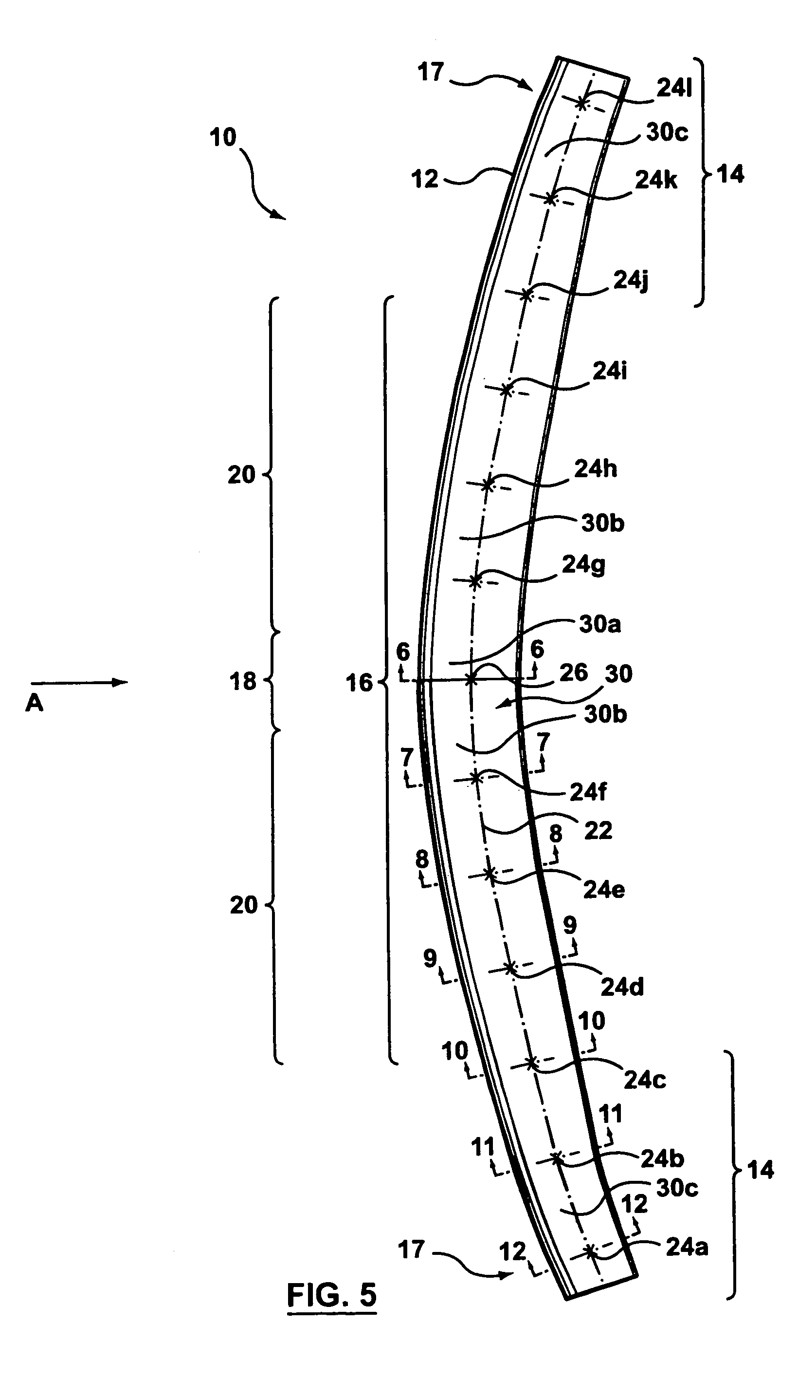
[0031]Referring to FIGS. 1 to 4, illustrated therein is a bumper 10 according to a preferred embodiment of the present invention. The bumper 10 comprises a hollow, longitudinally curved tubular beam 12 having two side rail mounting portions indicated generally at 14, and a front impact portion indicated generally at 16. The front impact portion 16 is disposed between the side rail mounting portions 14 and formed continuously therewith. When installed in a vehicle, the bumper 10 will be disposed behind and covered by a fascia 50 (as shown in FIG. 4). Preferably, the side rail mounting portions 14 are disposed at the ends 17 of the tubular beam 12.

[0032]The front impact portion 16 comprises an initial impact region 18 and two additional deforming regions 20. The initial impact region 18 is centrally disposed between the additional deforming regions 20, and will be the first part of the bumper to contact the barrier in the event of a front impact, although it will do so indirectly, as ...


PUM


Abstract

A bumper for a vehicle comprises a hollow tubular beam, and has two side rail mounting portions and a front impact portion disposed between and formed continuously with the side rail mounting portions. The front impact portion includes an initial impact region and two additional deforming regions, with the initial impact region being disposed between the additional deforming regions. The initial impact region has top and bottom surfaces that are generally flat and the additional deforming regions each have top and bottom surfaces that are generally convex.

Description

FIELD OF THE INVENTION[0001]The present invention relates generally to bumper beams for motor vehicles, and in particular to a hollow tubular bumper beam for a motor vehicle.BACKGROUND OF THE INVENTION[0002]Motor vehicles typically include a bumper and a fascia, i.e. a covering placed over the bumper to improve the vehicle's appearance and / or aerodynamics. Vehicle bumpers are designed to absorb the energy of a low speed collision so as to avoid damage to the rest of the vehicle. Thus, in the event of such a collision, only the bumper and the fascia would need to be replaced, thereby lowering repair costs. Space between the fascia and the bumper is typically filled with foam.[0003]In a low speed collision, for example at 5 miles per hour, a bumper will be expected to absorb a given amount of energy. The amount of energy (e) to be absorbed will be defined by the mass (m) and speed (v) of the vehicle, according to the formula e=(0.5)(m)(v2). Thus, in a test of a given vehicle at a give...

Claims


Application Information

Patent Timeline
Patent Type & Authority Patents(United States)
IPC IPC(8): B60R27/00B60R99/00B60R19/02B60R19/18
CPCB60R19/18B60R2019/1826
Inventor LIU, BINGMASON, MURRAY RICHARDZAJAC, RYSZARD ADAM
Owner F TECH R&D NORTH AMERICA
Why Eureka
Try Eureka