Intelligent collaboration across network systems

a network system and intelligent collaboration technology, applied in the field of network monitoring system and method, can solve the problems of ineffective approach, difficulty in attaching monitoring instruments to each of the network segments, and limitations as a technique for monitoring traffic within the switching device, so as to reduce the processing overhead in each switching devi

Inactive Publication Date: 2007-01-16
INMON
View PDF18 Cites 39 Cited by
  • Summary
  • Abstract
  • Description
  • Claims
  • Application Information

AI Technical Summary

Benefits of technology

[0010]It is another objective of the present invention to reduce the processing overhead in each switching device during network monitoring operations.

Problems solved by technology

The challenge is to monitor traffic on these segmented networks.
The use of point-to-point links makes it difficult to attach monitoring instrument to each of the network segments.
Furthermore, the large number of instruments required to monitor all the segmented parts of the network ensures that such an approach would not be cost effective.
In addition, because the switches and routers themselves have complex internal architectures, the flow of packets within, and through, them is becoming an important factor in network performance.
While this approach is suited to monitoring network segments, it has limitations as a technique for monitoring traffic within a switching device.
First, operating interfaces promiscuously imposes an additional load on the switching device (e.g. switch or router) since it would otherwise filter out a large fraction of the traffic on the segment and only concern itself with the packets that need to be switched or routed.
Second, knowing the traffic on the network segment provides no information about the amount of traffic that is entering the switching device or about the resources within the switching device that are being used to handle the traffic.
This is a time-based sampling system, and time-based sampling has been shown to be less accurate than packet count based sampling.
In addition, the Observer system does not provide for remote analysis of the time-based samples.
The cost of this instrument adds significant cost to the switch.
This technique requires considerable internal resources from the router or switch.
Adding NetFlow to a device adds significantly to its cost, especially in the low end and mid-range markets.
This technique also suffers from delay problems.
While this is acceptable for accounting purposes, it does not provide timely information for congestion management.

Method used


Image

  • Intelligent collaboration across network systems
  • Intelligent collaboration across network systems
  • Intelligent collaboration across network systems

Examples


Embodiment Construction

and its preferred embodiments, which description should be taken in conjunction with the accompanying drawings.

BRIEF DESCRIPTION OF THE DRAWINGS

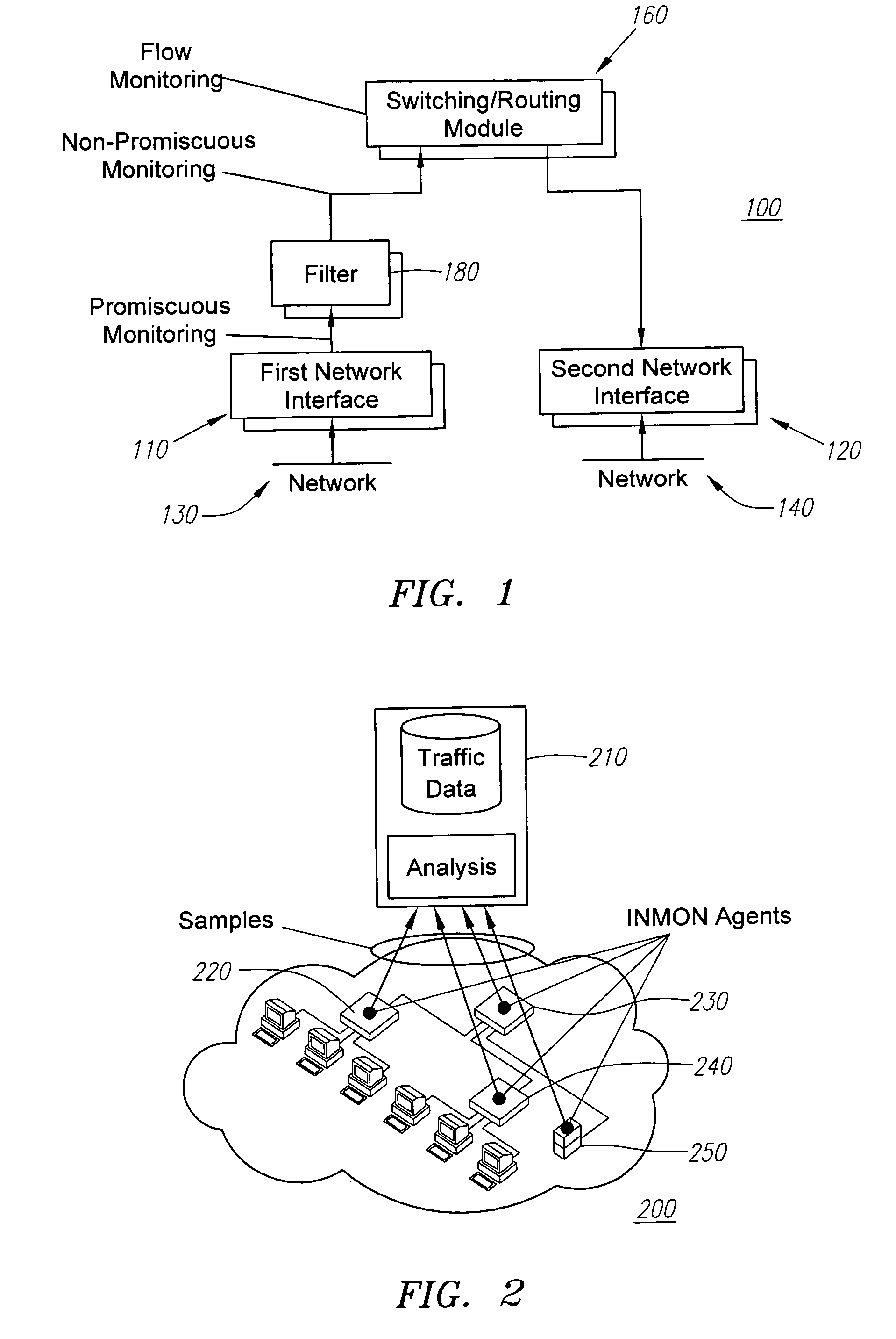
[0013]FIG. 1 shows logical entities within a typical switching device.

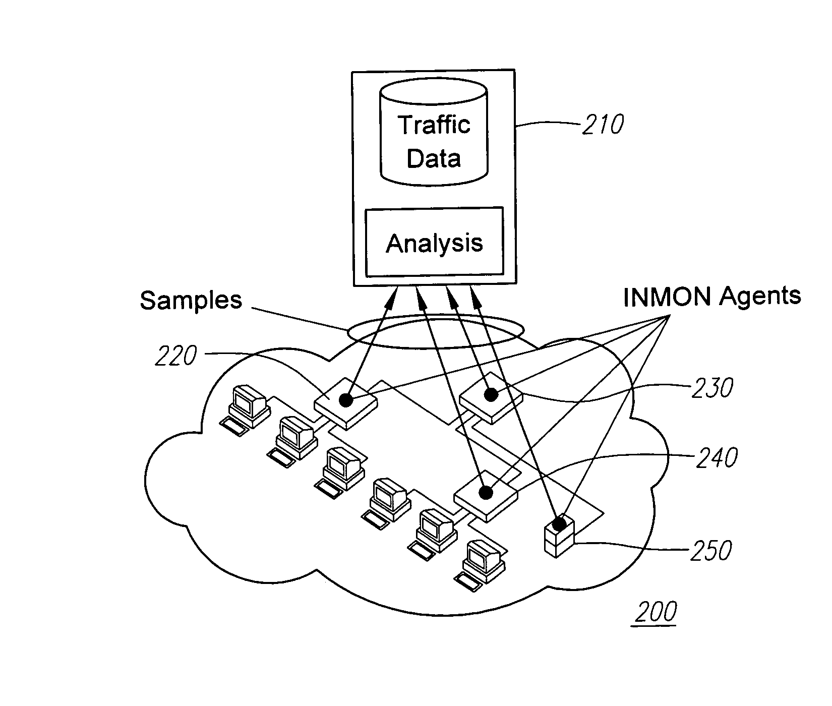
[0014]FIG. 2 shows a network monitoring system of a preferred embodiment according to the present invention.

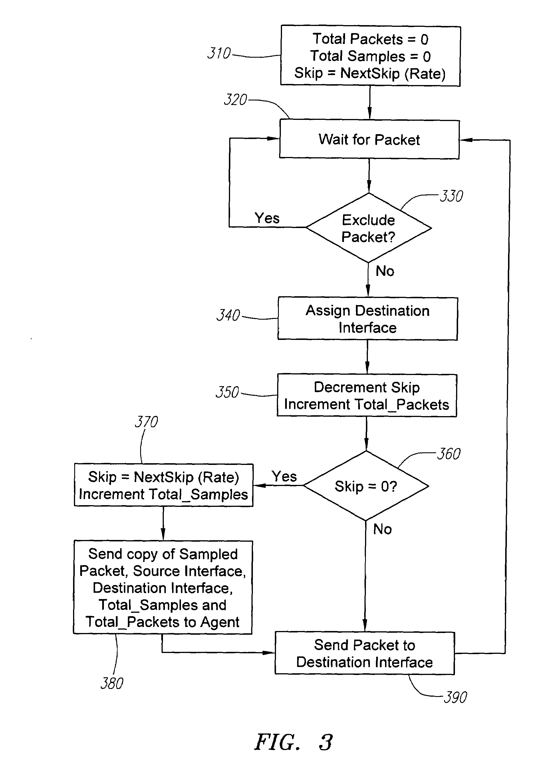
[0015]FIG. 3 shows the preferred steps for incorporating flow sampling in a switching / router module according to the present invention.

[0016]FIG. 4 shows the basic components of a monitor server of the preferred embodiment.

[0017]FIG. 5 shows a centralized switching device architecture according to the present invention.

[0018]FIG. 6 shows the components of a switch / router module using an ASIC circuitry and multiple network interfaces.

[0019]FIG. 7 shows how switching / routing modules can be connected using a single bus.

[0020]FIG. 8 shows another preferred embodiment using cross-bar interconnect linking switching modules together.

[0021]FIG. 9 shows the functional element...


PUM


Abstract

A network monitoring system and method for analyzing network traffic is provided. This network monitoring system and method employ flow monitoring to analyze the traffic flow inside a switching device. All message packets entering the switching device are filtered and then sampled. After message packets are sampled, the switching device generates reporting packets containing network information related to the sampled packets. These reporting packets are then transmitted to a monitor server for analysis. Generally, the monitor server is coupled to a number of the switching devices so that the overall performance of the network can be gathered and presented to the users.

Description

RELATED APPLICATION DATA[0001]This application is a continuation of U.S. patent application Ser. No. 09 / 438,680, filed Nov. 12, 1999 now U.S. Pat. No. 6,894,972.BACKGROUND OF THE INVENTION[0002]The present invention relates to a network monitoring system and method for monitoring the activity on a network carrying message packets where each of the message packets contains source and destination addresses.[0003]Traffic monitoring is a vital element of network and system management. Very little happens in a networked enterprise without producing some network traffic. Monitoring this traffic provides important information about the operation of enterprise applications. This information is essential for activities such as cost allocation, capacity planning, quality of service analysis, fault detection and isolation and security management.[0004]Traffic monitoring used to be a relatively straightforward task. In the past, a large number of machines was connected to a single shared networ...

Claims


Application Information

Patent Timeline
Patent Type & Authority Patents(United States)
IPC IPC(8): H04J1/16H04L12/24H04L12/26
CPCH04L43/065H04L43/022H04L41/046
Inventor PHAAL, PETER
Owner INMON
Why Eureka
Try Eureka