Method and apparatus for antenna array beamforming

Active Publication Date: 2007-01-16
GOOGLE TECH HLDG LLC
View PDF16 Cites 38 Cited by
  • Summary
  • Abstract
  • Description
  • Claims
  • Application Information

AI Technical Summary

Problems solved by technology

However, in many applications, especially data applications, the target subscriber unit is close to the base station, where self-interference is the dominant source of interference.
In these conditions, the existing method for optimizing the transmitter weighting coefficients can be highly non-optimal.
In addition, current methods for weighting the coefficients do not accou

Method used


Image

  • Method and apparatus for antenna array beamforming
  • Method and apparatus for antenna array beamforming
  • Method and apparatus for antenna array beamforming

Examples


Embodiment Construction

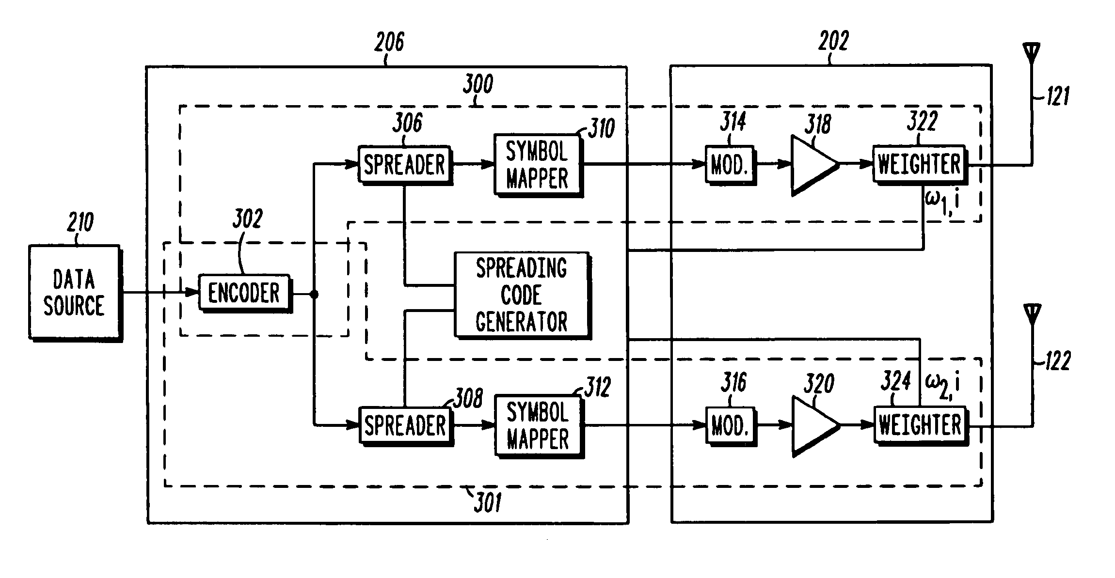
[0016]In order to optimize performance of an antenna array in a high multipath fading environment or in environments of significant self-interference or where intra-cell interference dominates inter-cell interference, an antenna array beamforming technique employs independent transmit weighting coefficients for multiple subscriber units served by a transmitting communication device. Optimization of the weighting coefficients is a joint, rather than an independent, venture of the multiple subscriber units. Joint optimization preferably is implemented at the transmitting communication device and involves the communication device optimizing based on knowledge of the channels between itself and each of the subscriber units, as well knowledge of the inter-cell and intra-cell interference observed at each of the subscriber units. Joint optimization of the weighting coefficients is a complex process, and to simplify the process optimization criteria are defined that allow the weighting coe...


PUM


Abstract

An antenna array beamforming technique employs independent transmit weighting coefficients for multiple subscriber units served by a transmitting communication device. Optimization of the weighting coefficients is a joint, rather than an independent, venture of the multiple subscriber units. Joint optimization preferably is implemented at the transmitting communication device and involves the communication device optimizing based on knowledge of the channels between itself and each of the subscriber units, as well as knowledge of the inter-cell and intra-cell interference observed at each of the subscriber units. Joint optimization of the weighting coefficients is a complex process, and to simplify the process optimization criteria are defined that allow the weighting coefficients corresponding to the subscriber units to be optimized independendy rather than jointly. Because this technique accounts for self-interference, it yields a weighting that is more nearly optimal than the current methods of transmit antenna array weighting.

Description

REFERENCE(S) TO RELATED APPLICATION(S)[0001]The present application claims priority from provisional application Ser. No. 60 / 188,177, entitled “Optimal Transmit Array Weighting for DS-CDMA with Channel Feedback,” filed Mar. 10, 2000, which is commonly owned and incorporated herein by reference in its entirety.”FIELD OF THE INVENTION[0002]The present invention relates to wireless telecommunication systems, and more particularly to the use of antenna arrays in wireless telecommunication systems.BACKGROUND OF THE INVENTION[0003]An important goal in designing a wireless communication system is to maximize system capacity, that is, to maximize a number of users that may simultaneously be served by the communication system. One way of increasing system capacity is to lower the transmit power allocated to each user. By lowering the allocated transmit power, interference for all users is lowered, which allows for the addition of new users to the system.[0004]One way to lower the transmit po...

Claims


Application Information

Patent Timeline
IPC IPC(8): H04B7/02H04B17/00H04B7/24H04B7/06
CPCH04B7/0632H04B7/063H04B7/0452H04B7/0617
Inventor FRANK, COLIN D.
Owner GOOGLE TECH HLDG LLC
Why Eureka
Try Eureka