
Continuous longitudinal flow root crop harvesting

a harvester and longitudinal technology, applied in the field of root crop harvesters, can solve the problems of beets that have to be especially rugged and bulky, beets that have to be moved in different directions, and the root crop harvester must be limited, so as to improve cleaning, improve cleaning, and improve cleaning

Active Publication Date: 2007-01-23
ARTS WAY MFG
View PDF35 Cites 21 Cited by
  • Summary
  • Abstract
  • Description
  • Claims
  • Application Information

AI Technical Summary

Benefits of technology

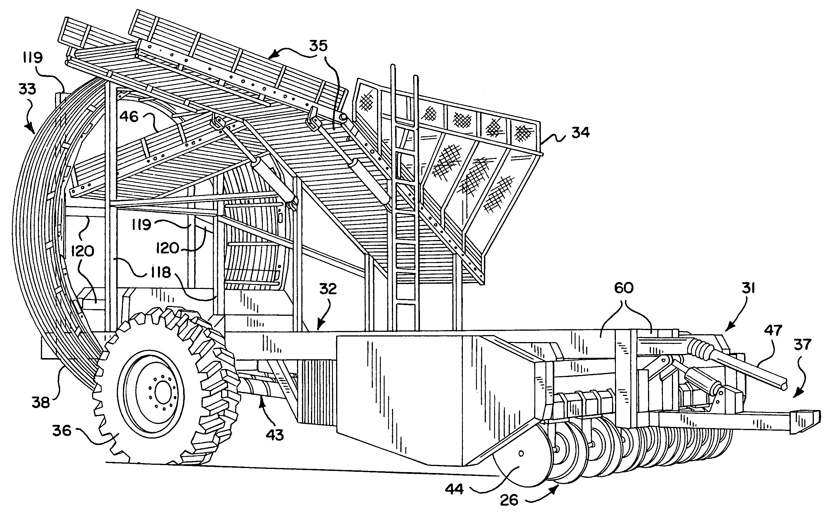
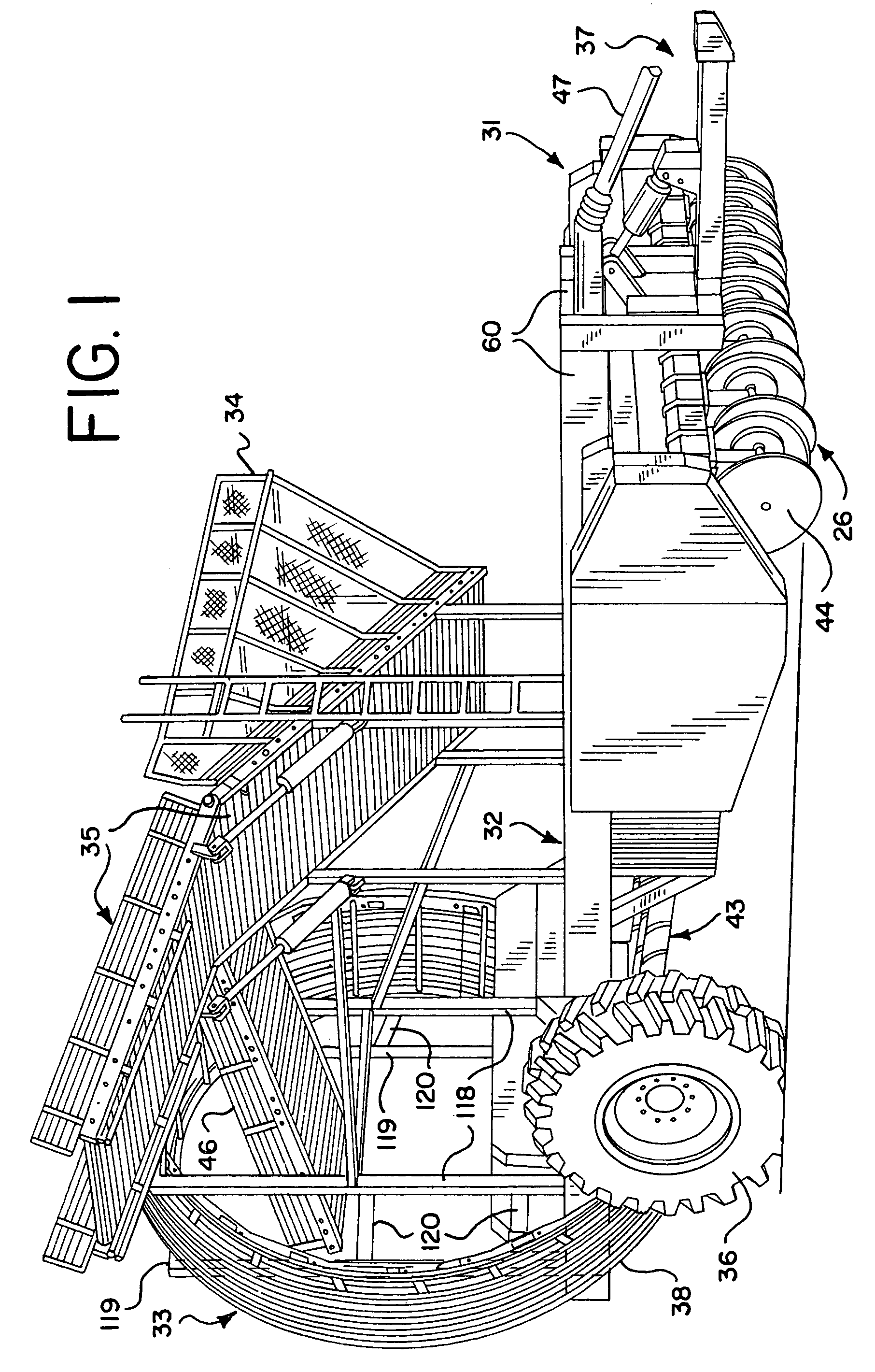
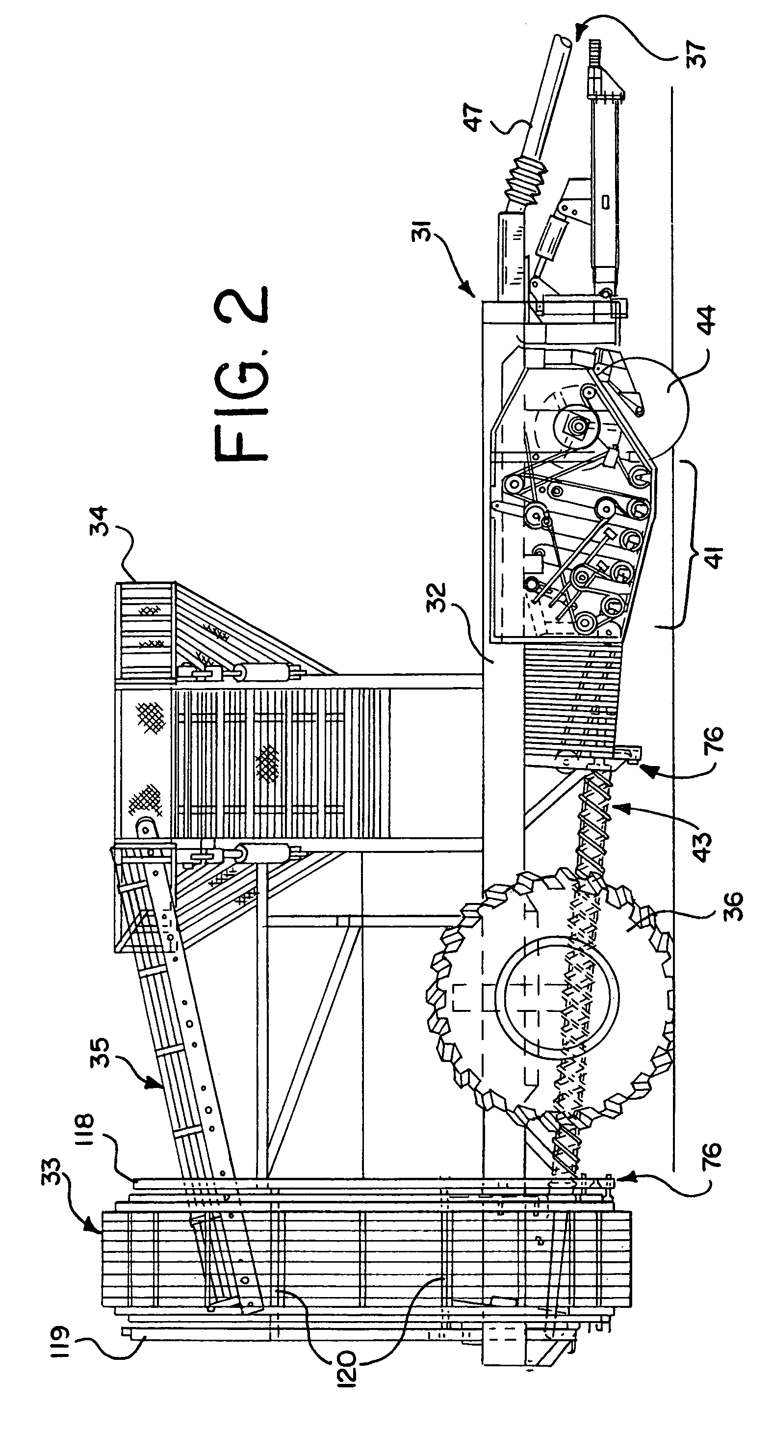
[0034]In accordance with the present invention, beet harvesters provide flexibility in meeting harvesting needs and improved cleaning capabilities. Preferably, modular components allow interchangeability of the header assembly depending upon row configurations and can also provide interchangeability, if desired, of the elevators as between a ferris wheel assembly and a scrubber chain assembly. Additionally, in a preferred embodiment, the grabrollers are longitudinally-disposed so as to improve cleaning by providing continuous rearward flow of the beets from a transfer assembly to a rear-loading elevator assembly.
[0035]In an embodiment of the invention, the harvester includes a pivoting tank conveyor which allows for evenly filling a holding tank. The invention also can have a transfer assembly which can be easily removed with a hand-actuated winch for cleaning and maintenance. The present invention also preferably includes large diameter ground-engaging wheels and a component layout which is selected to provide improved balance and maneuverability when compared with more traditional carrier wheels and component arrangements.

Problems solved by technology

Beet harvesters must be especially rugged and bulky in order to unearth sugarbeets and other root crops, with its attendant engagement with rocks and other obstacles along a typical beet harvesting path.
Root crop harvesters also have been limited by size constraints and root crop processing difficulties from achieving improved root crop cleaning along the root crop flow path of the harvester.
This problem, typically associated with prior art beet harvesters, is that they require the beets to change direction laterally along the cleaning flow path.
This in turn makes it more difficult for the rollers to rotate and clean the beets.
Traditionally, a beet harvester is configured with either a ferris wheel unit or a scrubber chain unit, and the user may not have the best unit for each harvesting situation.
), the design disclosed therein is plagued by a number of problems.
For one, the proposed harvester has poor lateral balance because the elevator assembly is offset from the centerline.
Also, the proposed harvester still requires the beets to turn the corner to travel from the cleaning rollers to the elevator assembly.

Method used


Image

  • Continuous longitudinal flow root crop harvesting
  • Continuous longitudinal flow root crop harvesting
  • Continuous longitudinal flow root crop harvesting

Examples


embodiment 38

[0100]With further reference to the elevator assembly 33, the ferris wheel embodiment 38 illustrated in FIG. 20 provides a lift of the beets after they drop off the end of the grabroller assembly 43 which is more gentle than other elevator arrangements. Preferably, the ferris wheel assembly is hydraulically driven and has a simplified arrangement with large ferris wheel rollers. It is typically driven at 11 rpm, although some conditions may require a slower speed of 9–10 rpm. A ferris wheel type of elevator assembly 33 is well known in the industry as a means of elevating beets for transport into an open-top holding tank 34.

[0101]The illustrated ferris wheel elevator assembly 38 is generally formed by several closely-spaced rails 108 that define a vertically extending ring. A conveyor lifts the beets from the bottom of the elevator to the top, while a retainer, which is not pictured, disposed within the ring provides a spring force that presses the beets against the inner surface of...

embodiment 39

[0103]The improved scrubber chain elevator assembly 39 shown in FIG. 22 requires less ground clearance because the outer chain 112 traverses the bottom section once instead of twice. The scrubber chain elevator embodiment 39 incorporates inner and outer belted chains 114 and 112, 42 inches wide in a preferred embodiment, which provide simple circular chains with natural tensioning for holding beets as they are lifted. Tighteners 54 are provided for both the inner and outer chains 114 and 112 of the scrubber chain elevator assembly 39. The motor of the illustrated scrubber chain elevator assembly 39 is hydraulically driven by the self-contained hydraulic subsystem with a flow control valve for adjusting the speed of the elevator assembly. A crossover return chain 112 is provided in the illustrated embodiment for increased clearance and additional cleaning. An S-drive 116 is provided on the outer chain 112, with a headshaft drive 117 on the inner chain 114.

[0104]Each of the elevator a...


PUM


Abstract

A harvester for root crops such as beets is provided which preferably provides continuous flow of root crops from a header, along a transfer assembly, through a processing run, and to an elevator assembly. The harvester can be configured to include or accommodate interchangeable header assemblies having different numbers of rows and / or row spacings. The transfer assembly can be of a floating type and helps to provide an even distribution of beets to the grabrollers. The processing run includes full-length cleaning grabrollers disposed parallel to the direction of travel. Modular elevator assemblies can be provided to further enhance harvester versatility. Such an approach includes interchangeable ferris wheel and scrubber chain elevator assemblies. An improved scrubber chain elevator assembly can be used which has a wraparound scrubber chain design. A pivoting tank conveyor for evenly filling a holding tank can be included. Large diameter carrier wheels on a single axle positioned for improved balance, flotation, and maneuverability typically are important basic characteristics of the harvesters.

Description

CROSS REFERENCE TO RELATED APPLICATION[0001]Provisional Patent Application Ser. No. 60 / 551,512, filed Mar. 9, 2004.BACKGROUND OF THE INVENTION[0002]1. Field of the Invention[0003]This invention generally relates to harvesters for and harvesting of crops that must be removed from the ground, more particularly, root crops such as beets.[0004]2. Description of Related Art[0005]Beet harvesters must be especially rugged and bulky in order to unearth sugarbeets and other root crops, with its attendant engagement with rocks and other obstacles along a typical beet harvesting path. Prior art beet harvester patents include U.S. Pat. No. 2,944,611 (Rollins), U.S. Pat. No. 3,010,522 (Oppel), U.S. Pat. No. 3,181,616 (Oppel), U.S. Pat. No. 4,116,279 (Kilburn), U.S. Pat. No. 4,137,973 (Schwitters), U.S. Pat. No. 4,184,550 (Ammermann), U.S. Pat. No. 4,226,566 (Maust), U.S. Pat. No. 4,382,471 (Peterson) and U.S. Pat. No. 4,633,956 (Glifberg). Prior art publications include those disclosing sugarbee...

Claims


Application Information

Patent Timeline
Patent Type & Authority Patents(United States)
IPC IPC(8): A01B25/00A01B17/00A01B19/00A01D13/00A01D19/00A01D19/02A01D19/04A01D25/00A01D25/04A01D33/00A01D33/08A01D33/10
CPCA01D19/04A01D33/08A01D33/00
Inventor TAYLOR, HOWARD W.BAUER, CHARLESVOGEL, WAYNE
Owner ARTS WAY MFG
Learn More