Positive action fenestration lock

a fenestration lock and positive action technology, applied in the field of snap locks, can solve the problem of limited pivot movement of the tongues by the handl

Active Publication Date: 2007-01-23
ROTO FASCO CANADA
View PDF20 Cites 35 Cited by
  • Summary
  • Abstract
  • Description
  • Claims
  • Application Information

AI Technical Summary

Benefits of technology

[0006]A first objective of the present invention is to provide a simple and reliable positive action fenestration lock.
[0009]A forth objective of the present invention is to provide a positive action fenestration lock with extended service life.

Problems solved by technology

Second, there is a limited pivot movement of the tongues by the handle.

Method used


Image

  • Positive action fenestration lock
  • Positive action fenestration lock
  • Positive action fenestration lock

Examples


Embodiment Construction

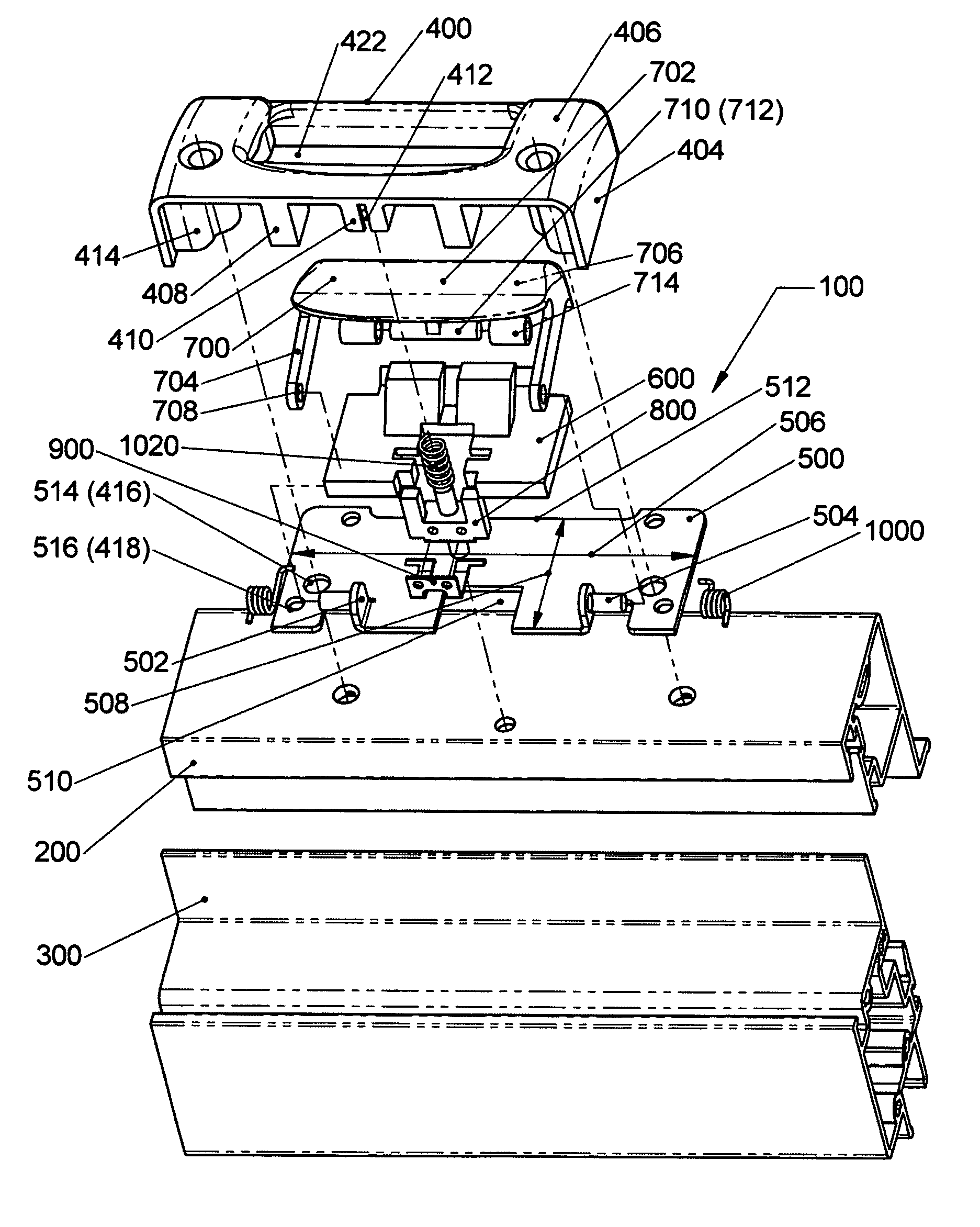
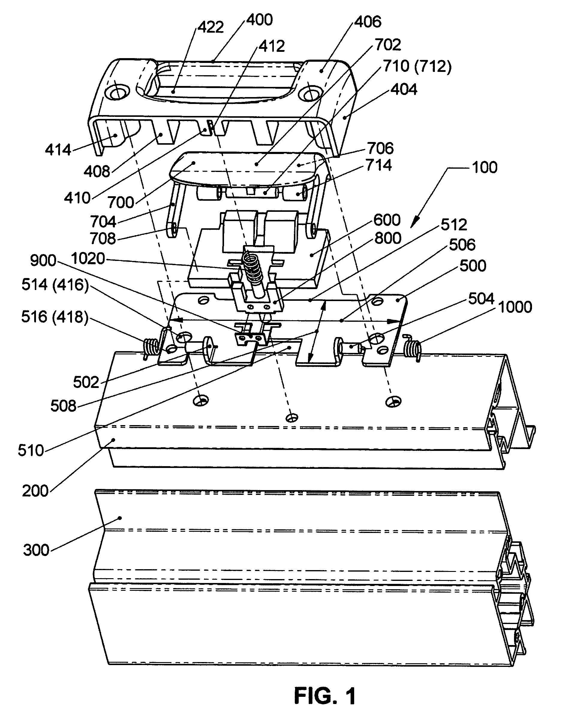
[0039]Referring to FIGS. 1 to 9″, a positive action fenestration lock 100, according to the present invention, is adaptable to be attached to a moving window profile 200 and to interact, by sliding, with a fixed window profile 300.

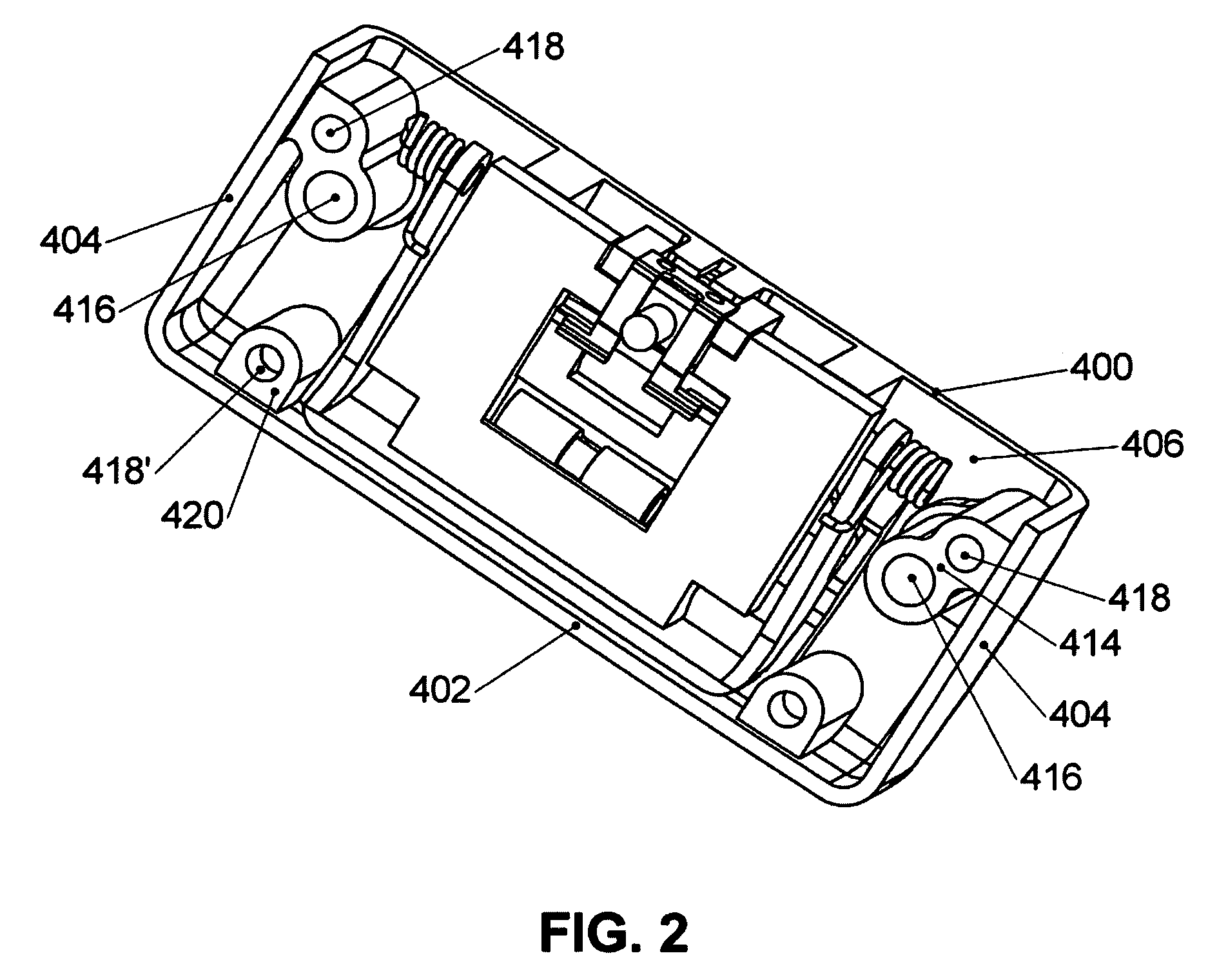
[0040]Basically, positive action fenestration lock 100 comprises[0041]a hollow body 400, closed by[0042]a base plate 500;[0043]a bolt-wedge 600, displaceable rectilinearly with respect to hollow body and base plate 400 and 500, respectively;[0044]a button 700, located generally in hollow body 400 and pivotally connected to base plate 500;[0045]an actuator 800 and a flat spring 900, the latter being attached to the former, control together the rectilinear movement of bolt-wedge 600, while the latter is activated by button 700;[0046]a pair of restoring torsion springs 1000, located between base plate and button 500 and 700, respectively, resist against a torque caused by button 700, the latter being adaptable to be finger pressed by an operator; and[0047]a h...


PUM


Abstract

A positive action fenestration lock, i.e. adaptable to be attached to a moving window profile and to interact, by sliding, with a fixed window profile, said positive action fenestration lock comprises: a hollow body closed by a base plate; a bolt-wedge displaceable rectilinearly with respect to the hollow body and the base plate, respectively; a button located generally in the hollow body and pivotally connected to the base; an actuator and a flat spring, the latter being attached to the former, controlling together the rectilinear movement of the bolt-wedge, while the latter is activated by the button; a pair of restoring torsion springs, located between the base plate and the button, for resisting against a torque caused by the button, the latter being adaptable to be finger pressed by an operator; and a helical compression spring acting permanently on the actuator and, impliedly, on the flat spring.

Description

I. BACKGROUND OF THE INVENTION[0001]1. Field of the Invention[0002]The present invention relates to snap locks in general and, more specifically, to a positive action fenestration lock, i.e. adaptable to be attached to a moving window profile and to interact, by sliding, with a fixed window profile.[0003]2. Description of the Prior Art[0004]The particular class of latches to which the present invention pertains uses latching plates with latching shoulders, between which a land to provide an abutment is formed. The latching shoulders are inclined with respect to a vertical surface of a widow frame. For example, U.S. Pat. No. 5,901,501 dated May 11, 1999 and granted to Fountaine for a “Window Fastener” describes a lock for use with a sliding sash window. The lock has a body with a handle mounted with the body for pivotal movement about a pivot axle. A latch tongue is operatively coupled to the handle and a latch tongue is provided with a latching surface for contacting an end of the l...

Claims


Application Information

Patent Timeline
Patent Type & Authority Patents(United States)
IPC IPC(8): E05C1/02E05C19/10
CPCE05B63/185E05B65/0864Y10S292/37Y10T292/0971Y10T292/096Y10T292/106Y10T292/1053
Inventor REBEL, JACOBZHANG, KAI
Owner ROTO FASCO CANADA
Why Eureka
Try Eureka