Connector and method of molding a connector

Inactive Publication Date: 2007-01-23
SUMITOMO WIRING SYST LTD
View PDF6 Cites 5 Cited by
  • Summary
  • Abstract
  • Description
  • Claims
  • Application Information

AI Technical Summary

Benefits of technology

[0010]The lock must be relatively wide in situations where the cavity is narrow. Thus, a proportion of the wall of the tab insertion hole to be cut is increased since the width of the mold-removal hole for forming the lock is set in accordance with the width of the lock. As a result, an area taken up by the preventing portion is smaller by this amount.
[0011]The preventing portions at the opposite first and second sides of the tab insertion hole are narrowed equally if the center of the lock coincides with the center of the cavity along the widthwise direction and areas of e

Problems solved by technology

Thus, neither preventing portion can sufficiently receive the

Method used


Image

  • Connector and method of molding a connector
  • Connector and method of molding a connector
  • Connector and method of molding a connector

Examples


Embodiment Construction

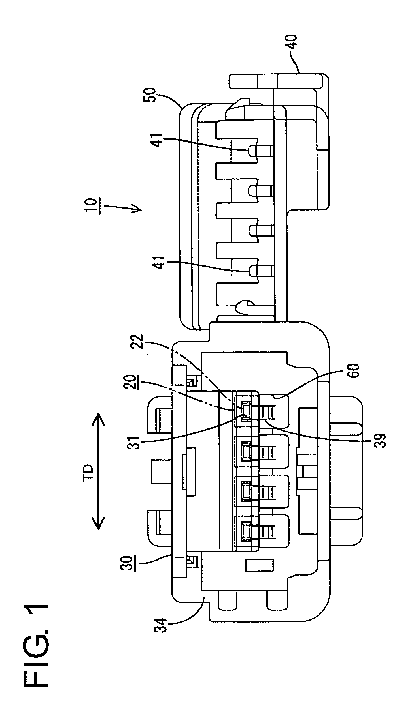
[0024]A connector according to the invention is identified by the numeral 10 in FIGS. 1 to 6. The connector 10 has a plurality of male terminal fittings 20, and a housing 30 made e.g. of a synthetic resin accommodates the terminal fittings 20. The end of the connector 10 that mates with a mating connector will be referred to herein as the front.

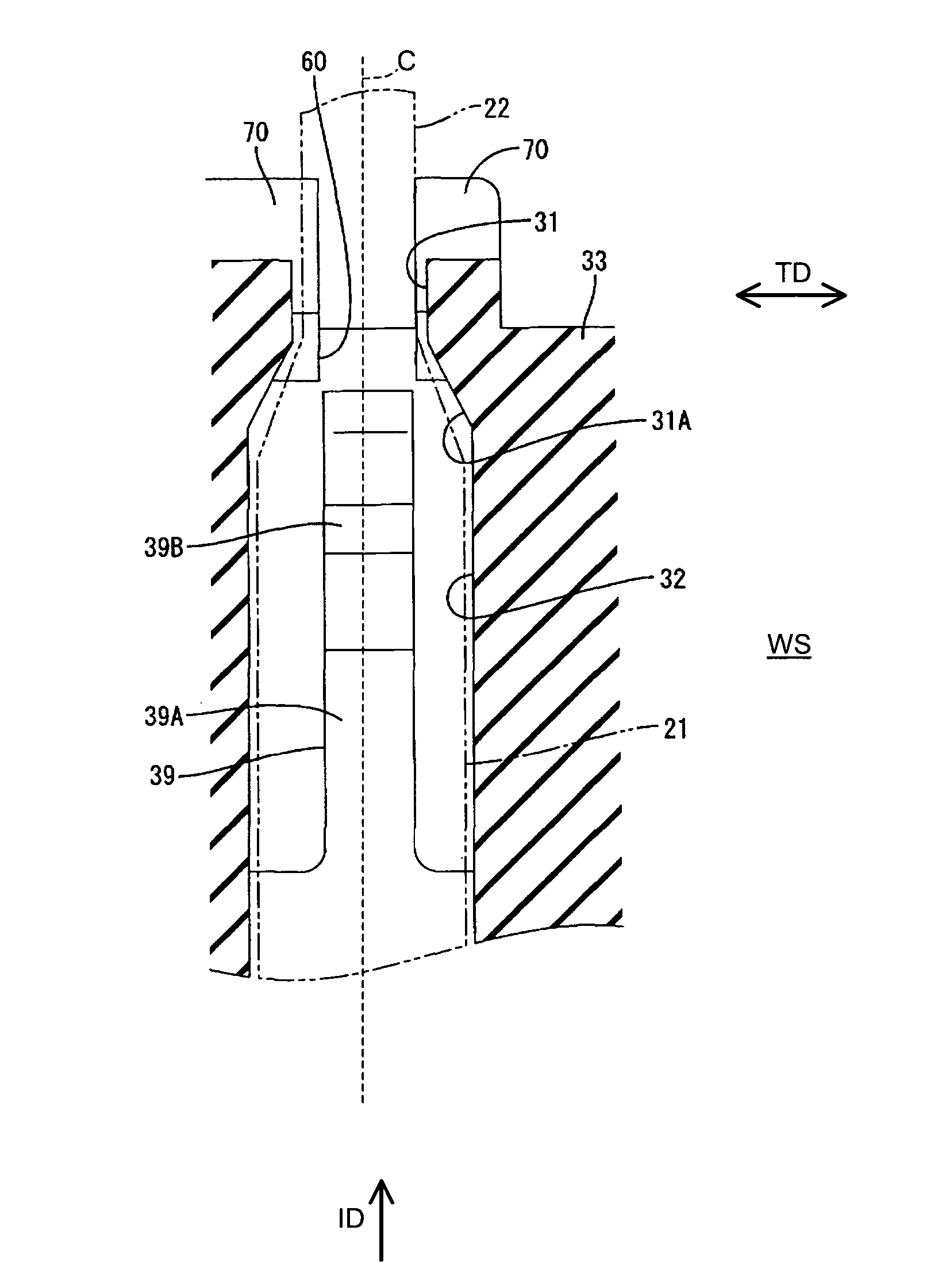
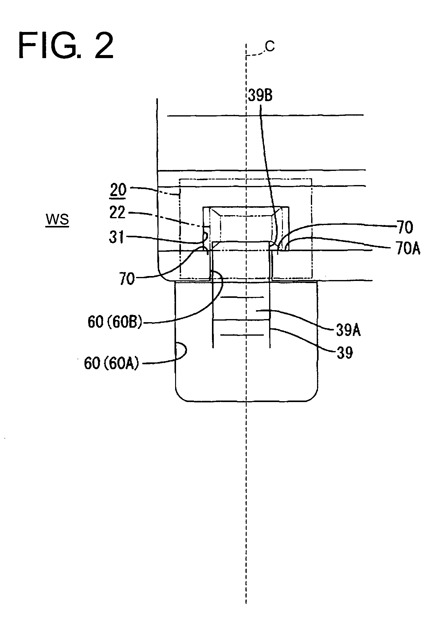
[0025]As shown in phantom in FIG. 5, each terminal fitting 20 has a substantially rectangular tubular main portion 21. A long narrow tab 22 projects forward from the main portion 21, and a wire crimping portion 23 extends back from the main portion 21. The wire crimping portion 23 is configured to be crimped, bent or folded into connection with an unillustrated wire. The tab 22 has a wide rectangular cross section, and slanted or rounded guiding surfaces 22A are formed at the leading end thereof. The bottom wall of the main portion 21 is partly cut or recessed to form a lock hole (not shown), and the upper wall thereof is partly cut or recess...


PUM


Abstract

A mold-removal hole (60) formed upon forming a locking portion (39) and communicating with a tab insertion hole (31) is formed before a locking portion (39) by partly cutting a wall of the tab insertion hole (31). As this mold-removal hole (60) is formed, preventing portions (70) for preventing a displacement of the tab (22) inserted into the tab insertion hole (31) toward the mold-removal hole (60) are formed on the wall of the tab insertion hole (31) at the lateral sides of the mold-removal hole (60) and at the opposite widthwise outer sides of the locking portion (39). By displacing the position of the locking portion (39) toward one widthwise side from the center of the cavity (32), the preventing portion (70) provided at the other side is set to have an increased area of engagement with the tab (22).

Description

BACKGROUND OF THE INVENTION[0001]1. Field of the Invention[0002]The invention relates to a connector with a lock for a terminal fitting.[0003]2. Description of the Related Art[0004]U.S. Pat. No. 5,256,083 discloses a female connector that has a housing with opposite front and rear ends. Cavities extend through the housing from the front end to the rear end, and female terminal fittings can be inserted into the cavities from behind. Locks are cantilevered forwardly from the bottom walls of the cavities and lock the terminal fittings in the cavities. A tab insertion hole is formed in the front wall of each cavity to permit the entrance of a tab of a mating male terminal fitting from the front.[0005]Mold-removal holes are formed in the front of the housing to accommodate molds required to form the cantilevered locks. The mold-removal holes cut into middle parts of the bottom surfaces of the tab insertion holes.[0006]FIG. 7 illustrates a male connector with a cavity construction similar...

Claims


Application Information

Patent Timeline
IPC IPC(8): H01R13/40H01R13/42H01R13/422H01R13/436H01R43/18
CPCH01R13/4223H01R43/18H01R13/436
Inventor FUKAMACHI, MAKOTOINOUE, KENJI
Owner SUMITOMO WIRING SYST LTD
Why Eureka
Try Eureka