Vent assembly with single piece cover

a technology of single-piece cover and vent assembly, which is applied in the direction of roofs, windows, transportation and packaging, etc., can solve the problems of difficult cleaning, dirt accumulation between the smaller cover member and the larger cover member, and the two-piece cover is erroneously perceived

Inactive Publication Date: 2007-01-23
SPECIALTY MFG CO INC
View PDF13 Cites 42 Cited by
  • Summary
  • Abstract
  • Description
  • Claims
  • Application Information

AI Technical Summary

Benefits of technology

[0009]This invention provides a vent assembly for the roof of a vehicle, such as a school or transit bus in which the cover is a single piece to provide a vent assembly that is leak proof, aesthetically pleasing and aerodynamically efficient when the vent assembly is attached to the vehicle roof.
[0010]The vent assembly includes a static vent whereby the interior of the vehicle is continuously vented to the atmosphere in such a way so as to prevent the ingress of rain water into the vehicle compartment. The vent assembly may also include a powered fan unit for venting the vehicle interior when static or eductive venting inadequate.
[0012]The vent assembly of the invention is characterized by a single piece cover that preferably has an upper surface that is impervious to water. The vent assembly cover is attached to a base that has a vent inlet. The vent assembly preferably includes a partition member that cooperates with the base and the cover to form a vent passage that leads from the vent inlet to a vent outlet at the aft end of the cover, the vent passage including barriers preventing any water taken into the vent outlet from reaching the vent inlet.

Problems solved by technology

First and foremost, the two-piece cover is erroneously perceived as providing a leakage path via the seam where the smaller cover member is attached to the larger cover member.
The seam between the smaller cover member and the larger cover member collects dirt and is difficult to clean.
Moreover, the two piece cover is not perceived as aesthetically pleasing or aerodynamically efficient.
'182 patent do not provide any venting in the closed position nor prevent the ingress of rain water into the passenger compartment in any of its venting positions.

Method used


Image

  • Vent assembly with single piece cover
  • Vent assembly with single piece cover
  • Vent assembly with single piece cover

Examples


Embodiment Construction

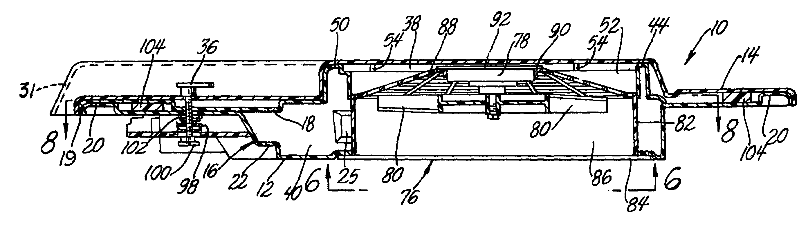
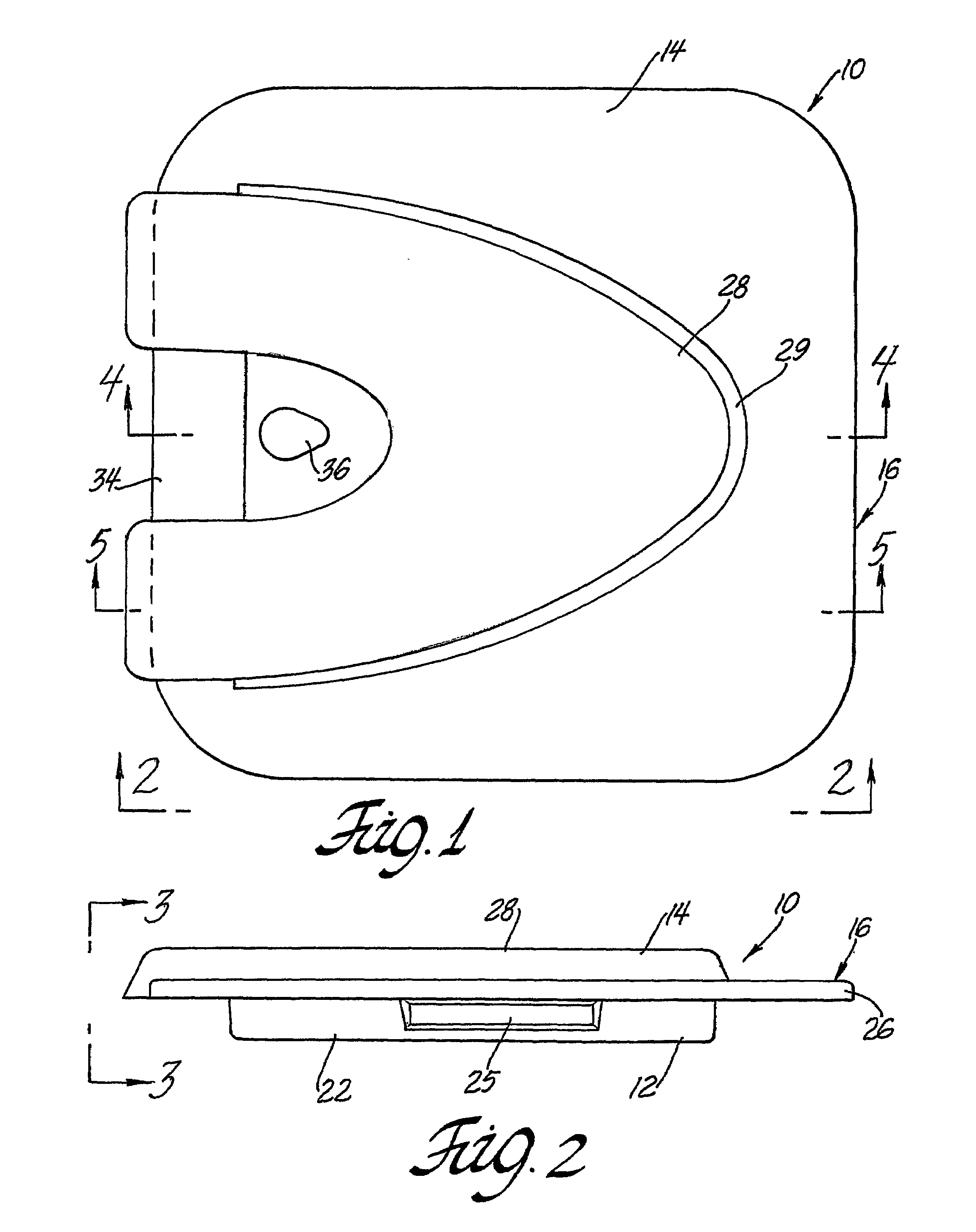
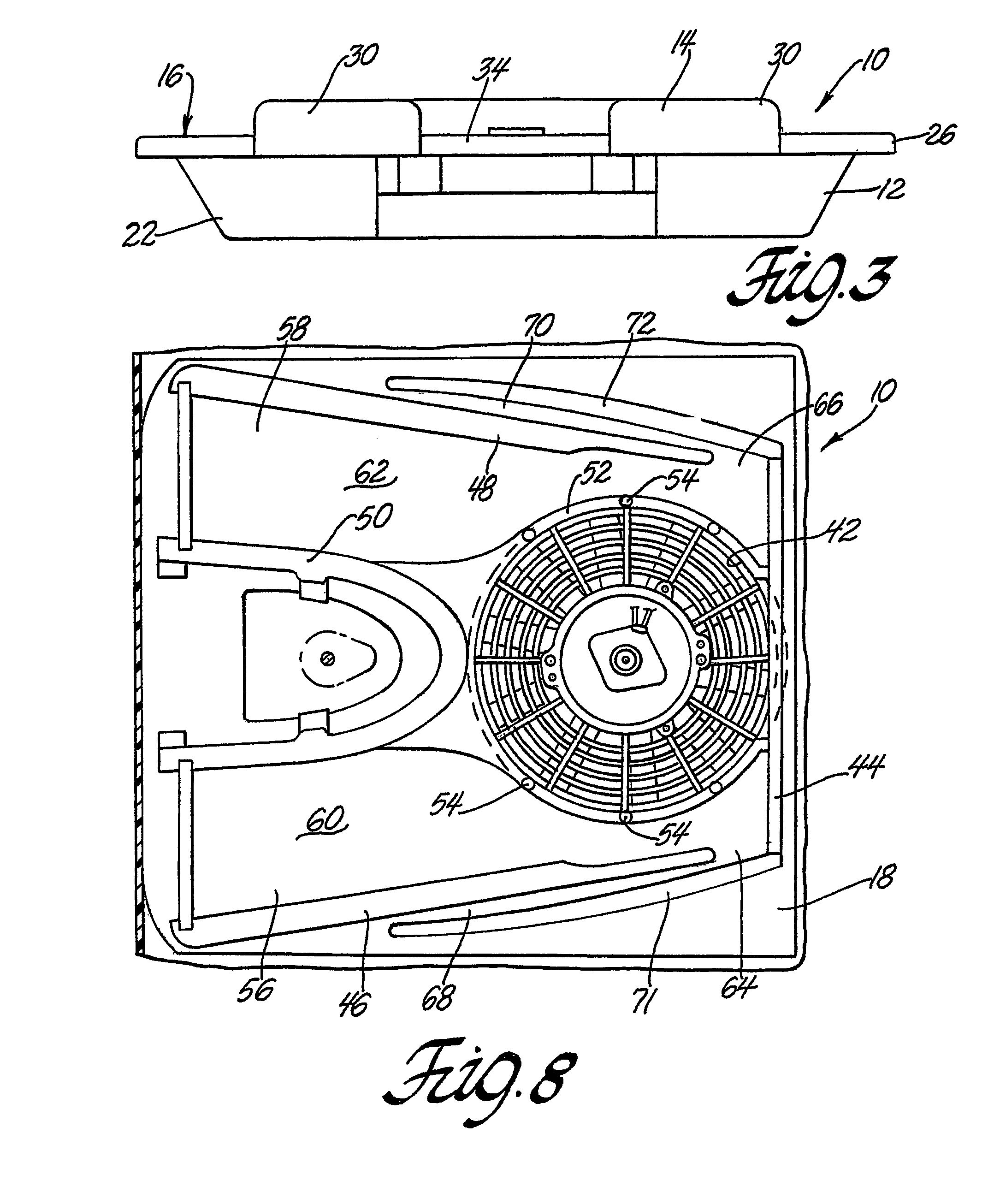
[0037]Referring now to the drawings, a vent assembly 10 according to the invention is disclosed. The vent assembly 10 comprises a base 12, a single piece cover 14 that is attached to base 12 to form a housing 16 and a partition 18 that is inside the housing to establish a vent path from an inlet in base 12 to an outlet in cover 14 and a water barrier to prevent the flow of water from the outlet in cover 14 back to the inlet in base 12.

[0038]Base 12 may be made economically from a sheet of plastic material that is formed to shape by thermo-forming or the like. Base 12 has a rim 20 that is preferably in the form of a downwardly open U-shaped section and continuous to provide a rigid attachment for cover 14. The central portion of base 12 is depressed to provide a pan 22. The bottom of pan 22 has generally rectangular opening that serves as an inlet 24 into the housing 16. The sides of the pan 22 have elongated finger depressions 25. Finger depressions are an optional feature for a com...


PUM


Abstract

A vent assembly has a base and a single piece cover that is attached to the base to form a housing. A partition inside the housing forms an upper compartment that communicates with an outlet at the rear of the cover and a lower compartment that communicates with an inlet through the base. The compartments communicate via an opening through the partition. The partition provides an exhaust passage from the opening to the outlet at the rear of the cover and a barrier to the flow of water from the outlet back to the opening. The partition and cover provide a drain passage from the exhaust passage back to the outlet in case water accumulates near the opening. The vent assembly may be static or include a fan unit to provide a powered vent assembly. Either may be used as the hatch of a combined vent and escape hatch assembly.

Description

RELATED APPLICATIONS[0001]This patent application claims priority of Provisional Patent Application No. 60 / 390,375 filed Jun. 21, 2002.FIELD OF THE INVENTION[0002]This invention relates to vent assemblies for mounting on vehicle roofs, particularly, roofs of school and transit busses.BACKGROUND OF THE INVENTION[0003]U.S. Pat. No. 4,592,269 granted to Ronald C. Lamparter Jun. 3, 1986 for a static vent device discloses a static vent assembly for a vehicle such as a school or transit bus wherein the interior of the vehicle is continuously vented to the atmosphere in such a way as to prevent the ingress of rain water into the passenger compartment.[0004]U.S. Pat. No. 4,895,065 granted to Ronald C. Lamparter Jan. 23, 1990 for a combined static and powered vent assembly discloses a combined static and powered vent assembly for a vehicle such as a school or transit bus wherein the interior of the vehicle is continuously vented to the atmosphere in such a way that the forward movement of th...

Claims


Application Information

Patent Timeline
Patent Type & Authority Patents(United States)
IPC IPC(8): B60H1/26B60H1/00B60H1/24B60J1/20B60J7/22
CPCB60H1/262
Inventor HAIGH, JAMES A.IMINSKI, RICHARD J.TRUSCOTT, PHILIP K.
Owner SPECIALTY MFG CO INC
Why Eureka
Try Eureka