
Methods for forming a fluted composite

a composite material and composite material technology, applied in the field of composite material forming methods, can solve the problems of gel blocking of absorbent composite materials that contain superabsorbent materials, requiring significant energy for their complete drying, and not being used commercially

Inactive Publication Date: 2007-01-23
NAT INST FOR STRATEGIC TECH ACQUISITIONS & COMMLIZATION
View PDF143 Cites 99 Cited by
  • Summary
  • Abstract
  • Description
  • Claims
  • Application Information

AI Technical Summary

Benefits of technology

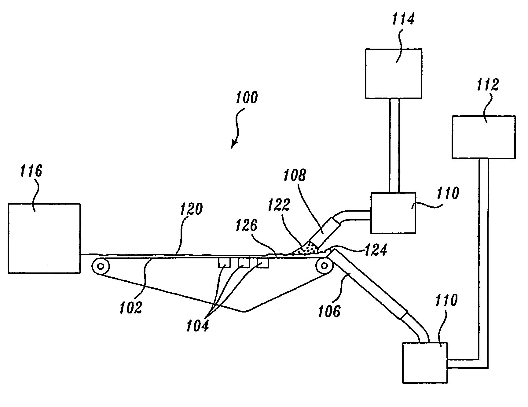
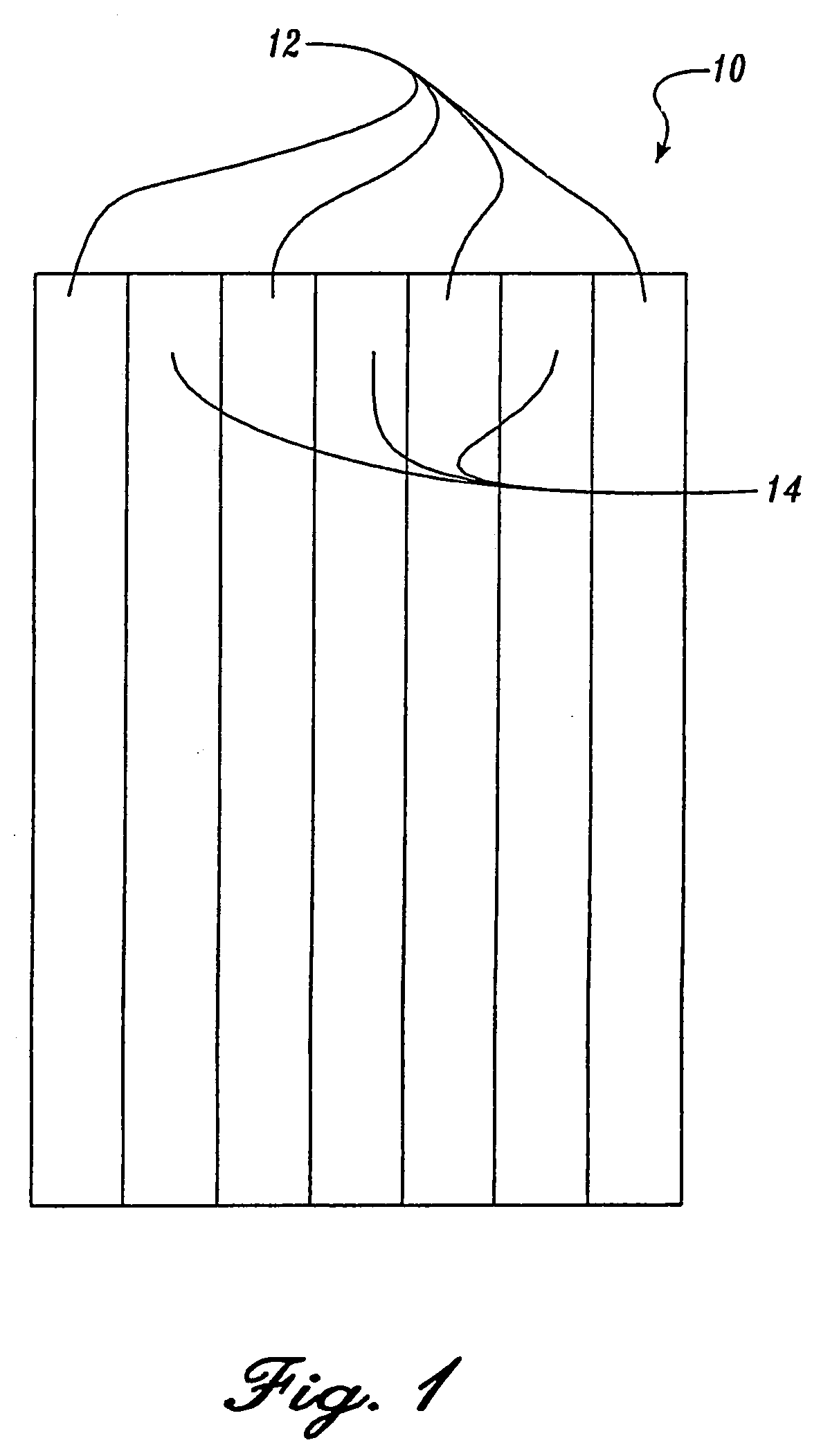
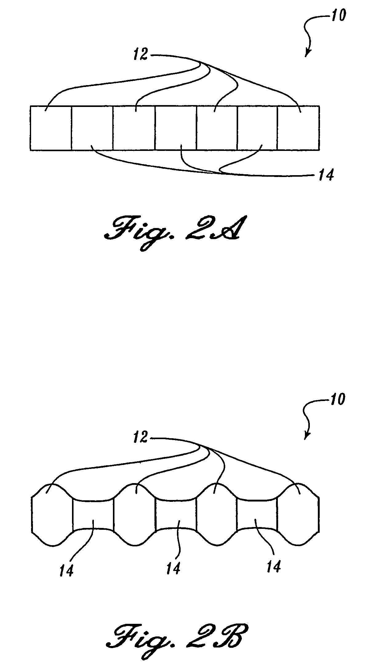
"The present invention provides methods for making an absorbent fibrous composite by depositing a fibrous slurry on a support and adding absorbent material across the width of the composite. The resulting composite has absorbent material in bands along its length. Drying the composite creates a fluted material with improved absorbency. The methods can be used with either a wet-laid or foam-forming process, and preferably twin-wire forming methods."

Problems solved by technology

Wet-laid processes for forming cellulose mats have not been used commercially because superabsorbent polymers tend to absorb liquid and swell during formation of the absorbent mats, thus requiring significant energy for their complete drying.
However, absorbent composites that contain superabsorbent materials commonly suffer from gel blocking.
By preventing distribution of acquired liquid from a composite's unwetted portions, gel blocking precludes the effective and efficient use of superabsorbent materials in fibrous composites.
The wicking capacity of conventional fibrous composites that include relatively homogeneous distributions of superabsorbent material is generally significantly restricted after initial liquid insult.
The diminished capacity of such fibrous composites results from narrowing of capillary acquisition and distribution channels that accompanies superabsorbent material swelling.
The diminution of absorbent capacity and concomitant loss of capillary distribution channels for conventional absorbent cores that include superabsorbent material is manifested by decreased liquid acquisition rates and far from ideal liquid distribution on successive liquid insults.

Method used


Image

  • Methods for forming a fluted composite
  • Methods for forming a fluted composite
  • Methods for forming a fluted composite

Examples


example 1

Acquisition Times for a Representative Fluted Absorbent Composite

[0171]In this example, the acquisition time for a representative fluted absorbent composite (Composite A) is compared to a commercially available diaper (Diaper A, Kimberly-Clark). Also included in the comparison is an absorbent composite (Composite B) having a composition similar to the composite and composed of fibers (50:50 crosslinked fibers and southern pine pulp fibers), wet strength agent, and absorbent material distributed relatively uniformly throughout the composite. The formation of Composite B is described in provisional U.S. patent application Ser. No. 60 / 046,395, filed May 13, 1997, and international application Serial No. PCT / US98 / 09682, filed May 12, 1998, assigned to Weyerhaeuser Company, each expressly incorporated herein by reference.

[0172]The tests were conducted on commercially available diapers (Kimberly-Clark) from which the core and surge management layer were removed and used as surrounds for t...

example 2

Acquisition Rate and Rewet for Representative Fluted Absorbent Composites

[0178]In this example, the acquisition time and rewet of representative fluted absorbent composites (designated Composites A1–A4) are compared to a commercially available diaper (Diaper A, Kimberly-Clark). Composites A1–A4 differ by the method by which the composites were dried. Also included in the comparison are a series of absorbent composites (Composites B1–B4) formed as described above for Composite B in Example 1 and differing by the method by which they were dried.

[0179]Certain properties of the tested composites including the amount of superabsorbent polymeric material (weight percent SAP) in the composite and basis weight for each of the composites are summarized in Table 2.

[0180]The tests were conducted on commercially available diapers (Kimberly-Clark) from which the cores were removed and used as surrounds for the fluted absorbent composites and for Composites B1–B4. The test diapers were prepared b...

example 3

Horizontal and Vertical Wicking for a Representative Fluted Absorbent Composite

[0190]In this example, the wicking characteristics of a representative fluted absorbent composite (Composite A) are compared to a commercially available diaper storage core (Diaper B, Procter & Gamble) and a wet-laid storage core having absorbent material distributed uniformly throughout the composite (Composite B).

[0191]The horizontal wicking test measures the time required for liquid to horizontally wick preselected distances. The test is performed by placing a sample composite on a horizontal surface with one end in contact with a liquid bath and measuring the time required for liquid to wick preselected distances. Briefly, a sample composite strip (40 cm×10 cm) is cut from a pulp sheet or other source. If the sheet has a machine direction, the cut is made such that the 40 cm length of the strip is parallel to the machine direction. For absorbent composites, the strip is centered such that four bands o...


PUM

PropertyMeasurementUnit
densityaaaaaaaaaa
densityaaaaaaaaaa
densityaaaaaaaaaa

Abstract

Methods for forming an absorbent fibrous composite containing absorbent material dispersed in bands through the composite and along the composite's length are disclosed. The methods generally include depositing a fibrous slurry on a foraminous support to form a web and depositing or injecting absorbent material into the web across its width to provide a web having absorbent material in bands along the composite's length. Drying the web provides a fluted absorbent composite. In one embodiment, the method is a wetlaid method and in another embodiment, the method is a foam-forming method. Preferably, the methods are twin-wire forming methods.

Description

CROSS-REFERENCE TO RELATED APPLICATIONS[0001]This application is a continuation of U.S. patent application Ser. No. 10 / 679.835, filed Oct. 6, 2003, now abandoned, which is a continuation of U.S. patent application Ser. No. 09 / 664,576, filed Sep. 18, 2000, now U.S. Pat. No. 6,630,054, which is a continuation of International Application No. PCT / US99 / 05997, filed Mar. 18, 1999, which claims the benefit of U.S. Provisional Application No. 60 / 078,779, filed Mar. 19, 1998, U.S. Provisional Application No. 60 / 082,771, filed Apr. 23, 1998, U.S. Provisional Application No. 60 / 082,790, filed Apr. 23, 1998, and U.S. Provisional Application No. 60 / 111,845, filed Dec. 11, 1998, the benefit of the priority of the filing dates of which are hereby claimed under 35 U.S.C. §§120 and 119, respectively. Each of the applications is incorporated herein by reference in its entirety.FIELD OF THE INVENTION[0002]The present invention relates to methods for forming an absorbent composite and, more particular...

Claims


Application Information

Patent Timeline
Patent Type & Authority Patents(United States)
IPC IPC(8): D21H23/14D21H13/02A61F13/15D21F9/00D21F11/00D21F11/04D21F11/14
CPCA61F13/15617D21H11/20A61F13/15699A61F13/534A61F13/536D21C9/002D21F9/006D21F11/002D21F11/006D21F11/04D21F11/14A61F13/15658A61F2013/1539A61F2013/4581A61F2013/530386A61F2013/530481
Inventor GRAEF, PETER A.BOLSTAD, CLIFFORD R.HOWARD, FRED B.MILLER, CHARLES E.BUNKER, DANIEL T.
Owner NAT INST FOR STRATEGIC TECH ACQUISITIONS & COMMLIZATION
Learn More