Oil filter cartridge

a technology of oil filter cartridge and oil filter cartridge, which is applied in the field of vehicles to achieve the effects of reducing leakage paths, minimizing space, and reducing piping and bracketry

Inactive Publication Date: 2007-01-23
DEERE & CO
View PDF21 Cites 2 Cited by
  • Summary
  • Abstract
  • Description
  • Claims
  • Application Information

AI Technical Summary

Benefits of technology

[0010]It would therefore be desirable to provide a hydraulic fluid system for utility tractors and similar vehicles which would minimize the piping and bracketry required to mount the filter and strainer outside of and adjacent the transmission case and its fluid reservoir, reduce the leak paths associated with plumbing joints required to house the filters and strainers in series and minimize the space required adjacent to the transmission case to mount and access the filter and strainer components. It would also be desirable to provide a design which would eliminate the parasitic horsepower loss caused by pulling hydraulic fluid through the strainer at all times.
[0011]Towards these ends, there is provided a disposable filter and strainer assembly with the bypass valve built into the strainer. This assembly utilizes a minimal amount of metal and is therefore incinerable. The bypass valve operates to direct hydraulic oil around the filter and through the strainer only when the oil viscosity is high. The valve then closes when the viscosity has been reduced to an acceptable level, allowing the oil to be pulled through the filter only. The parasitic horsepower loss found in many present hydraulic systems utilizing series plumbing is thereby eliminated with the present invention.
[0012]The disposable filter is further located in a specially constructed housing within the transmission case so that it is immersed within the hydraulic fluid at all times. In this way the filter and strainer are better assured a constant supply of hydraulic fluid to minimize the likelihood that pump cavitation and / or starvation will occur. Additionally, the space required adjacent to the transmission to house the filter and strainer assembly is minimized.
[0013]With the present invention there is provided a filter / strainer assembly which minimizes the piping, bracketry and space required to mount the filter strainer cartridge, makes access to it for servicing easier, better assures that the filter strainer has a constant supply of hydraulic fluid and eliminates the parasitic horsepower loss in the system caused by the need to always pull fluid through the strainer.

Problems solved by technology

This assembly utilizes a minimal amount of metal and is therefore incinerable.

Method used


Image

  • Oil filter cartridge
  • Oil filter cartridge
  • Oil filter cartridge

Examples


Embodiment Construction

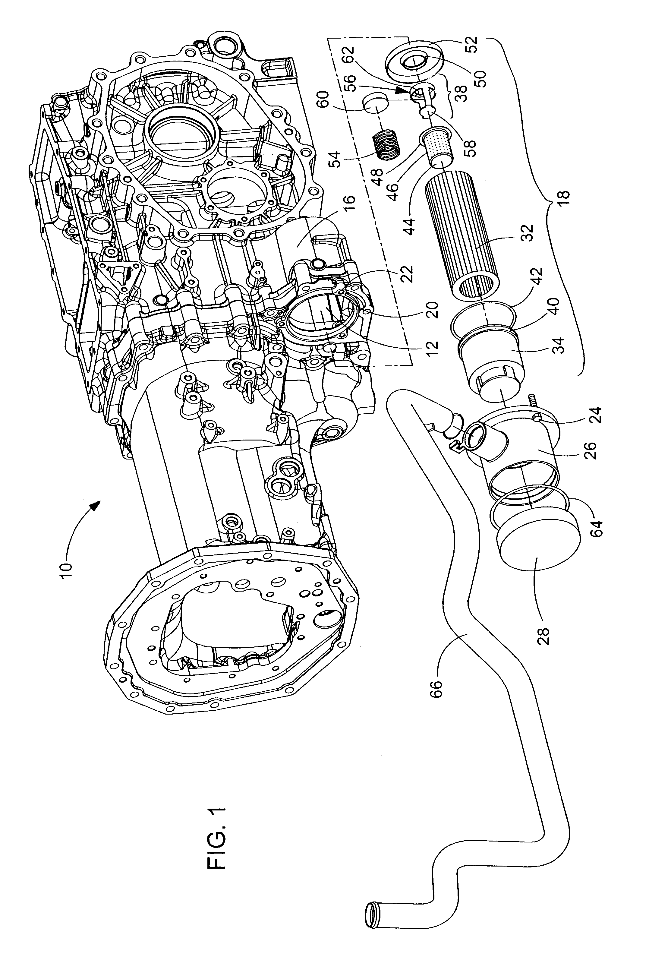
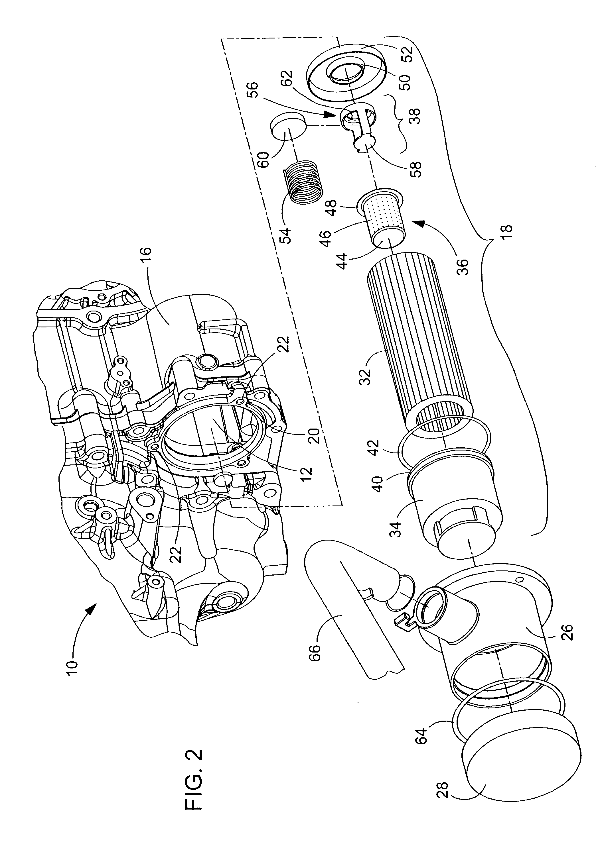
[0021]Looking first to FIG. 1, there is illustrated a transmission case 10 that houses the various components of a transmission as well as the oil reservoir 12 for the hydraulic fluid used by the transmission and the various hydraulic system functions 14 of the vehicle. Looking as well to FIG. 2, it can be seen that the transmission case 10 includes a housing 16 for the oil filter assembly 18 in the lower rear side of the case 10. This housing 16 is located so that the oil filter assembly 18 is immersed within the oil reservoir 12 contained in the lower portion of the transmission case 10. The opening 20 to the housing 16 is generally circular and provided with holes 22 for receiving bolts or similar fasteners 24.

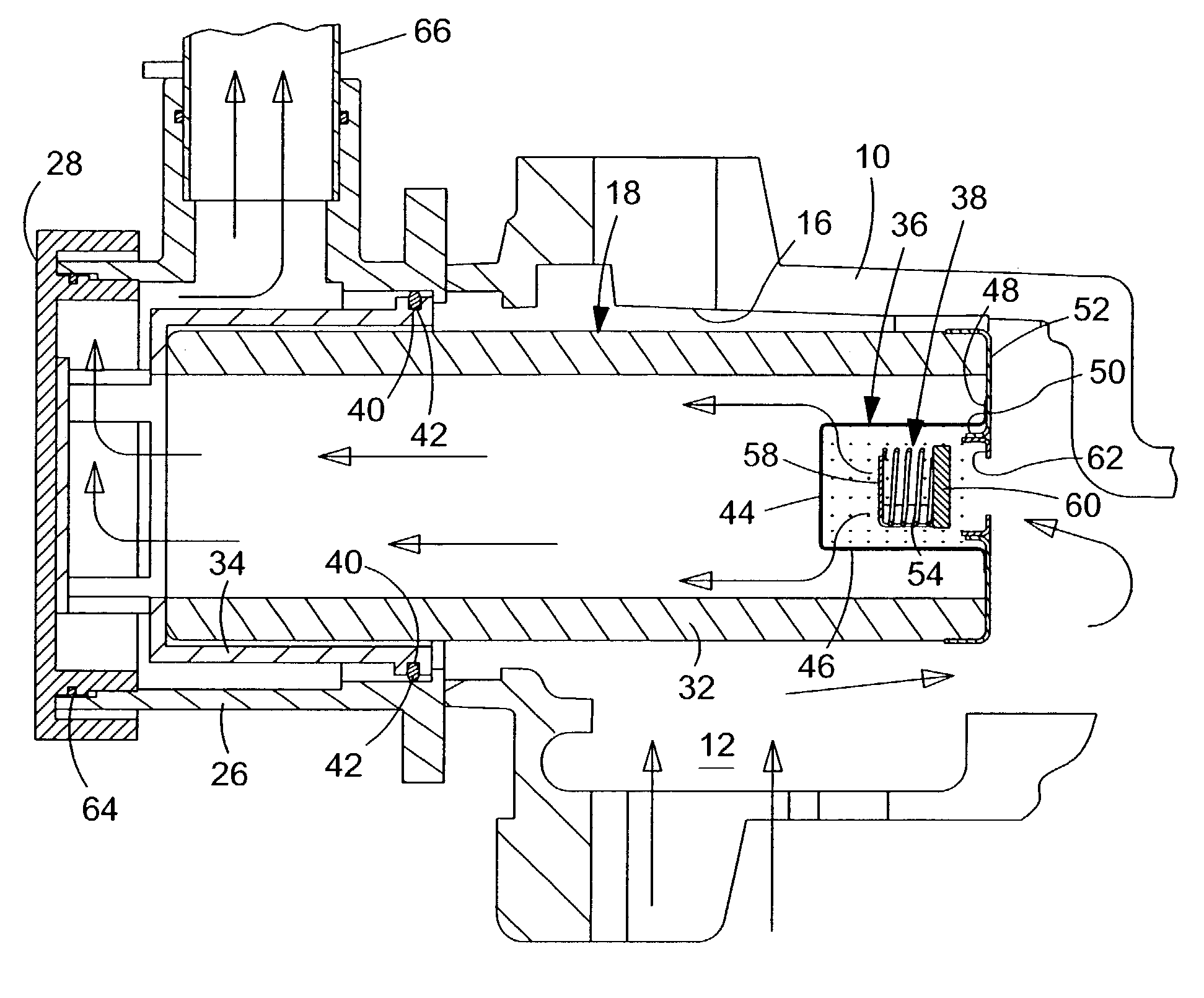
[0022]Receivable within the oil filter housing 16 is the combination hydraulic oil filter / strainer / bypass-valve assembly 18 shown in an exploded fashion in both FIGS. 1 and 2. A cutaway view of this assembly 18 is shown in FIG. 3 as it is supported by a cast filter head 26....


PUM

PropertyMeasurementUnit
pressureaaaaaaaaaa
sizesaaaaaaaaaa
sizesaaaaaaaaaa

Abstract

The present invention relates to small vehicles such as lawn and garden tractors and more specifically to an oil filter cartridge or assembly usable with the transmissions of such vehicles. The cartridge is comprised of a filtering element, a strainer element and a by-pass valve. The by-pass valve is housed within the strainer element and is adapted to direct oil flow through the strainer element, but not the filter element when the oil viscosity is high and only through the filter element when the oil viscosity is low. In this way, the parasitic horsepower loss caused by routing oil through the strainer element at all times is eliminated. The cartridge is also housed within the transmission case to reduce mounting bracketry outside the transmission case and minimize the likelihood of insufficient oil supply available for the filter, pump and hydraulic system functions.

Description

CROSS REFERENCE TO RELATED APPLICATIONS[0001]Two commonly owned and related patent applications have been filed concurrently with this patent application on Feb. 21, 2003, and their disclosures are intended to be fully incorporated by reference herein. They include “Tank Mounted Oil Filter Assembly”, Ser. No. 10 / 372,753, now U.S. Pat. No. 7,056,432, and “Fluid Line Locking Structure”, Ser. No. 10 / 372,752, now U.S. Pat. No. 6,871,883.FIELD OF THE INVENTION[0002]The present invention relates to vehicles such as utility tractors and more specifically, to a disposable hydraulic oil filter / strainer assembly which can be housed within the oil reservoir of the transmission and quickly and easily be removed and replaced.BACKGROUND OF THE INVENTION[0003]Small vehicles such as utility tractors utilize transmissions such as hydrostatic and clutch driven units. These transmissions rely upon hydraulic oil pumps to circulate the fluid from a reservoir located within the transmission case, through...

Claims


Application Information

Patent Timeline
Patent Type & Authority Patents(United States)
IPC IPC(8): B01D35/147B01D29/21
CPCB01D29/21B01D35/147B01D29/35B01D29/54
Inventor SMITH, ELLIS JUNIOR
Owner DEERE & CO
Why Eureka
Try Eureka