Tank mounted oil filter assembly
- Summary
- Abstract
- Description
- Claims
- Application Information
AI Technical Summary
Benefits of technology
Problems solved by technology
Method used
Image
Examples
Embodiment Construction
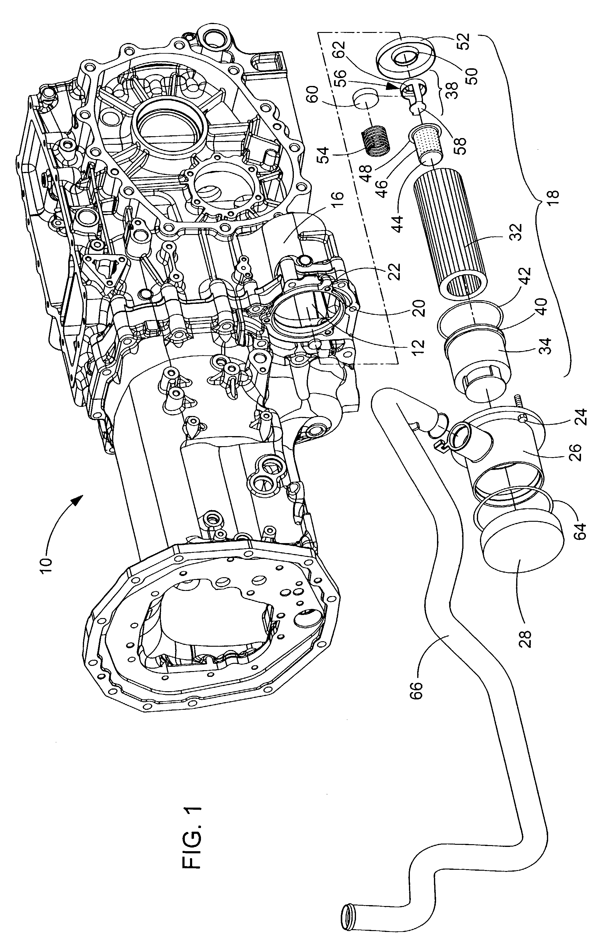
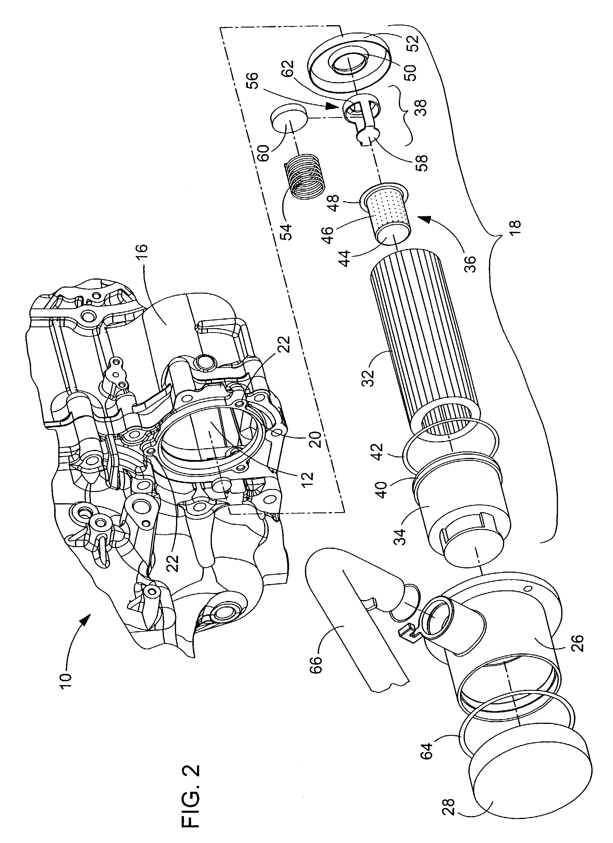
[0021]Looking first to FIG. 1, there is illustrated a transmission case 10 that houses the various components of a transmission as well as the oil reservoir 12 for the hydraulic fluid used by the transmission and the various hydraulic system functions 14 of the vehicle. Looking as well to FIG. 2, it can be seen that the transmission case 10 includes a housing 16 for the oil filter assembly 18 in the lower rear side of the case 10. This housing 16 is located so that the oil filter assembly 18 is immersed within the oil reservoir 12 contained in the lower portion of the transmission case 10. The opening 20 to the housing 16 is generally circular and provided with holes 22 for receiving bolts or similar fasteners 24.
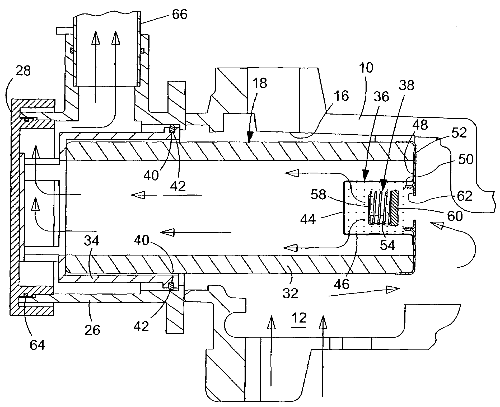
[0022]Receivable within the oil filter housing 16 is the combination hydraulic oil filter / strainer / bypass-valve assembly 18 shown in an exploded fashion in both FIGS. 1 and 2. A cutaway view of this assembly 18 is shown in FIG. 3 as it is supported by a cast filter head 26....
PUM
| Property | Measurement | Unit |
|---|---|---|
| Viscosity | aaaaa | aaaaa |
| Responsivity | aaaaa | aaaaa |
Abstract
Description
Claims
Application Information
 - R&D
- Intellectual Property
- Life Sciences
- Materials
- Tech Scout
- Unparalleled Data Quality
- Higher Quality Content
- 60% Fewer Hallucinations
Browse by: Latest US Patents, China's latest patents, Technical Efficacy Thesaurus, Application Domain, Technology Topic, Popular Technical Reports.
© 2025 PatSnap. All rights reserved.Legal|Privacy policy|Modern Slavery Act Transparency Statement|Sitemap|About US| Contact US: help@patsnap.com


