Fabrication of electrical medical leads employing multi-filar wire conductors

a technology of multi-filar wire and lead body, which is applied in the direction of auxillary welding devices, coupling device connections, therapy, etc., can solve the problems of degrading the insulation or fracture of lead conductors, untoward effects on performance and patient well-being, and the number of separate lead conductors that can be incorporated in a lead body of a given diameter is limited in this coaxial winding approach

Active Publication Date: 2007-01-30
MEDTRONIC INC
View PDF13 Cites 33 Cited by
  • Summary
  • Abstract
  • Description
  • Claims
  • Application Information

AI Technical Summary

Benefits of technology

[0016]In accordance with one aspect of the present invention, a cut end of such a stranded wire conductor is subjected to electrical current sufficient to heat and weld the strands together upon discharge of a high voltage between the stranded wire cut end and a ground metal plate. The discharge of weld energy from a weld energy source between the stranded wire cut end and the ground plate induces heat in the wire strands at the stranded wire cut end and the ground plate sufficient to melt and transfer conductive material from the ground plate into the interstices between the cut ends of the wire strands that solidifies to fuse the wire strands together. The fusing inhibits unraveling of the wire strands at the fused cut end, whereby the insertion of the stranded wire cable through a lead body lumen and the connection of the fused stranded wire cut end to a further lead component, e.g., a proximal lead connector element or distal electrode, is facilitated.
[0019]Furthermore, use of a material for the ground plate that is common to a material of the wire strands ensures that no contamination of the wire material is introduced in the transfer of material of the ground plate into the interstices of the wire strands.
[0023]Advantageously, the low electrical resistance of such silver core wires of the stranded wire conductor ensures that the current of the electrical arc between the stranded wire cut end and the ground plate is maximized without unduly heating the stranded wire conductor itself. Moreover, the diameter of the stranded wire conductor is not increased when the fusing takes place forming a weld mass.

Problems solved by technology

Over the years of implantation, the lead conductors and insulation are subjected to cumulative mechanical stresses as well as material reactions that can result in degradation of the insulation or fractures of the lead conductors with untoward effects on performance and patient well being.
The number of separate lead conductors that can be incorporated in a lead body of a given diameter is limited in this coaxial winding approach.
The exposed proximal and distal cable connection end sections can be damaged or can be frayed in the course of cutting or trimming the insulation from the 7×7 cable or 1×19 cable proximal end and distal end.
But, tinning with low melting temperature metals, other than perhaps molten silver, would introduce compounds or elements that would not necessarily be bio-compatible and that could degrade the insulating materials or make the “tinned” ends difficult to mechanically and electrically attach to a connector element or electrode.
Laser welding the 7×7 cable or 1×19 cable proximal and distal ends to prevent fraying requires relatively bulky, expensive, precision laser welding equipment as can be seen from the three laser beam equipment disclosed in the above-referenced '056 patent that increases costs of fabrication.

Method used


Image

  • Fabrication of electrical medical leads employing multi-filar wire conductors
  • Fabrication of electrical medical leads employing multi-filar wire conductors
  • Fabrication of electrical medical leads employing multi-filar wire conductors

Examples


Embodiment Construction

[0033]In the following detailed description, references are made to illustrative embodiments of methods and apparatus for carrying out the invention. It is understood that other embodiments can be utilized without departing from the scope of the invention.

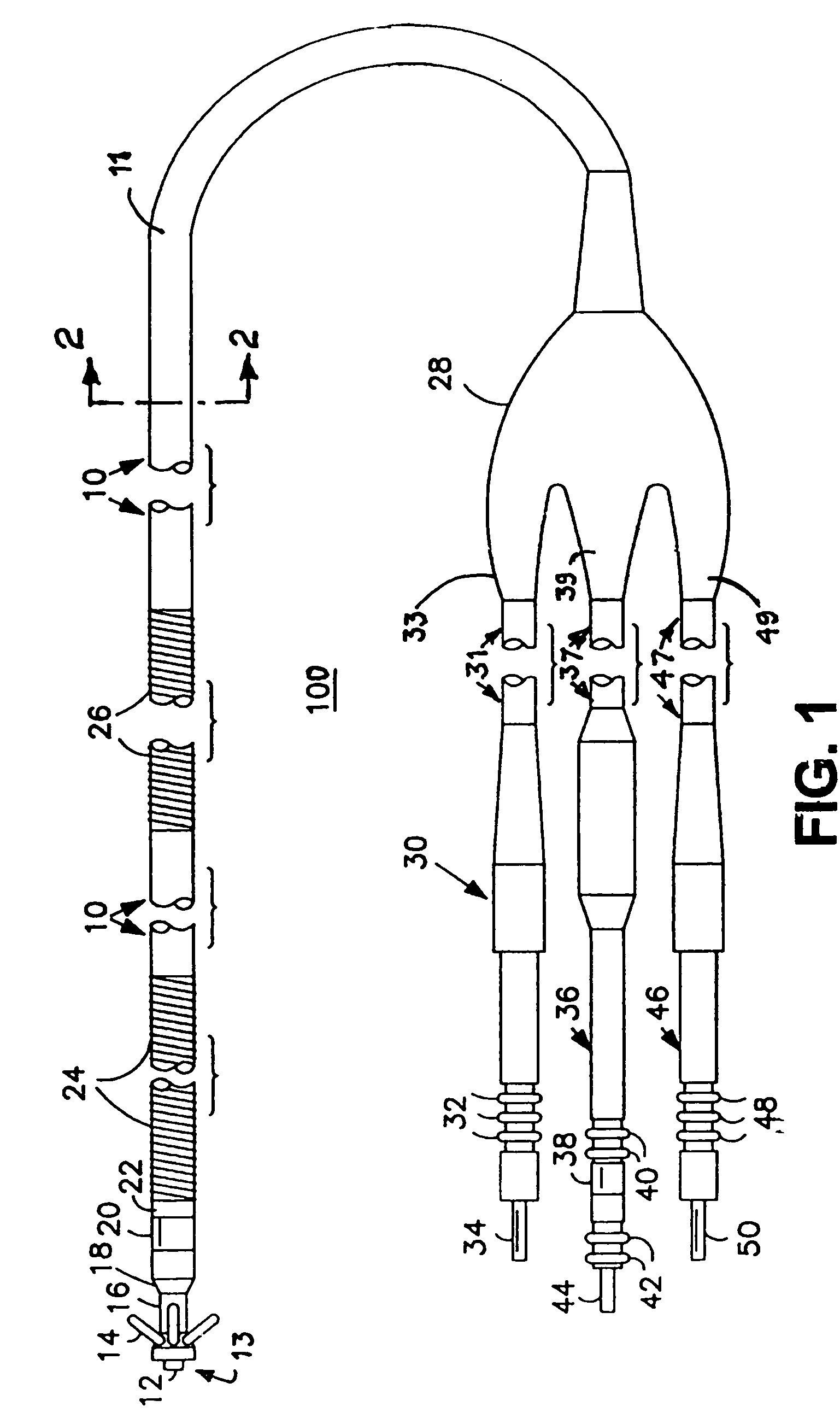
[0034]FIG. 1 therefore illustrates an exemplary cardiac lead 100, particularly and endocardial ICD lead of the type disclosed in the above-referenced '625 patent, in which the present invention is advantageously practiced. The lead 100 comprises an elongated lead body 10 extending between proximal lead connector assemblies 30, 36 and 46 and a lead body distal end 13. The lead body 10 is a complex structure having distinct proximal, intermediate, and distal regions having four lead lumens through which four electrical lead conductors that are electrically insulated from one another by the lead body insulator extend.

[0035]The distal region of the lead 100 includes a number of components, in this embodiment, including an elongated, op...


PUM

PropertyMeasurementUnit
lengthaaaaaaaaaa
lengthaaaaaaaaaa
Shore hardnessaaaaaaaaaa

Abstract

During fabrication of an electrical medical lead, a cut end of a stranded wire conductor is subjected to electrical current sufficient to heat and weld the strands together upon discharge of a high voltage between the cut end and a ground metal plate formed of a material of the stranded wire conductor. The discharge of weld energy between the stranded wire cut end and the ground plate induces heat in the wire strands at the stranded wire cut end and the ground plate sufficient to transfer conductive material from the ground plate to fuse the wire strands together. The fusing inhibits unraveling of the wire strands at the fused cut end, whereby the insertion of the stranded wire cable through a lead body lumen and the connection of the fused stranded wire cut end to a further lead component, e.g., a proximal lead connector element or distal electrode, is facilitated.

Description

FIELD OF THE INVENTION[0001]The present invention relates to fabrication of implantable electrical medical leads intended for chronic implantation in the body and particularly to electrical medical leads for applying electrical stimulation to and / or sensing electrical activity of the body, particularly cardiac leads for applying electrical stimulation to and / or sensing electrical activity of the heart at one or more electrode positioned at a cardiac implantation site within a heart chamber or cardiac vessel adjacent a heart chamber.BACKGROUND OF THE INVENTION[0002]Implantable electrical medical stimulation and / or sensing leads intended for chronic implantation in the body are well known in the fields of cardiac stimulation and monitoring, including cardiac pacing and cardioversion / defibrillation (C / D), and in other fields of electrical stimulation or monitoring of electrical signals or other physiologic parameters.[0003]An implantable cardioverter / defibrillator (ICD) implantable pul...

Claims


Application Information

Patent Timeline
Patent Type & Authority Patents(United States)
IPC IPC(8): H01R43/02A61B5/04A61N1/00B23K1/002B23K31/00B23K37/00H01R43/04
CPCA61N1/056H01R13/5224H01R43/0214Y10T29/49174Y10T29/49192Y10T29/49179H01R2201/12
Inventor CALZADA, JAVIER E.LEON, JAIMESANTIAGO TORRES, JORGE L.
Owner MEDTRONIC INC
Why Eureka
Try Eureka