Quick coupling for hydraulic fluid pipes

Active Publication Date: 2007-01-30
PARKER HANNIFIN PAK
View PDF7 Cites 14 Cited by
  • Summary
  • Abstract
  • Description
  • Claims
  • Application Information

AI Technical Summary

Benefits of technology

[0004]The object of the present invention is therefore to provide an arrangement making possible this connection, allowing the tubular coupling part to move with respect to the outer tubular part, even in the presence of a hydraulic pressure inside the female connection element.
[0006]Consequently, when the moving coupling part is inserted into the outer tubular part of the female element, the seal separating the chamber in which a hydraulic pressure prevails from the chamber at atmospheric pressure will be situated opposite at least one slot, making it possible to remove the compressive force exerted by the seal and allowing hydraulic liquid to escape toward the chamber at atmospheric pressure. With the pressure in the female element thus having dropped, the male element will be able to be locked and the moving coupling part will return to its initial position in which sealing is reinstated.
[0012]This arrangement makes it possible to bring the chamber subjected to hydraulic pressure into progressive communication with the chamber subjected to atmospheric pressure.

Problems solved by technology

The problem which arises is that during the coupling phase, in the course of which the moving coupling part enters the outer tubular part, the pressure existing on the female part side, inside a pipe or inside the receiver, tends to oppose the connection.

Method used


Image

  • Quick coupling for hydraulic fluid pipes
  • Quick coupling for hydraulic fluid pipes
  • Quick coupling for hydraulic fluid pipes

Examples


Embodiment Construction

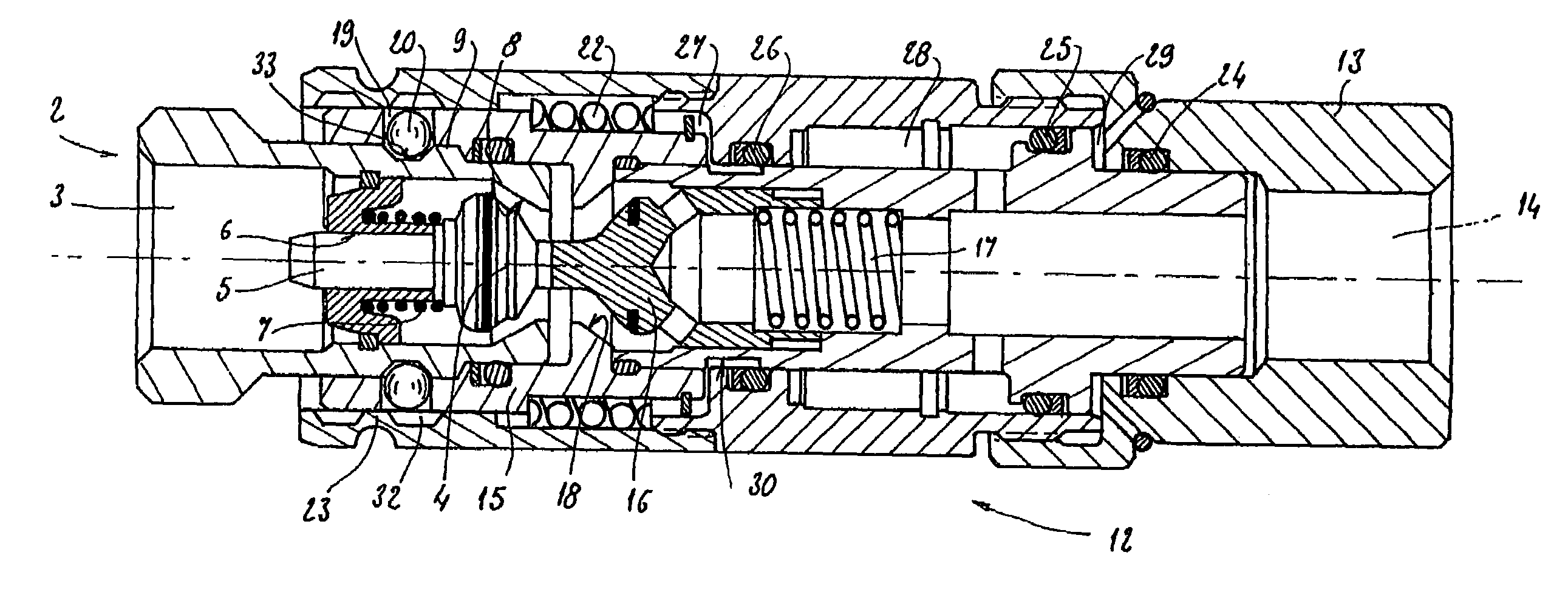
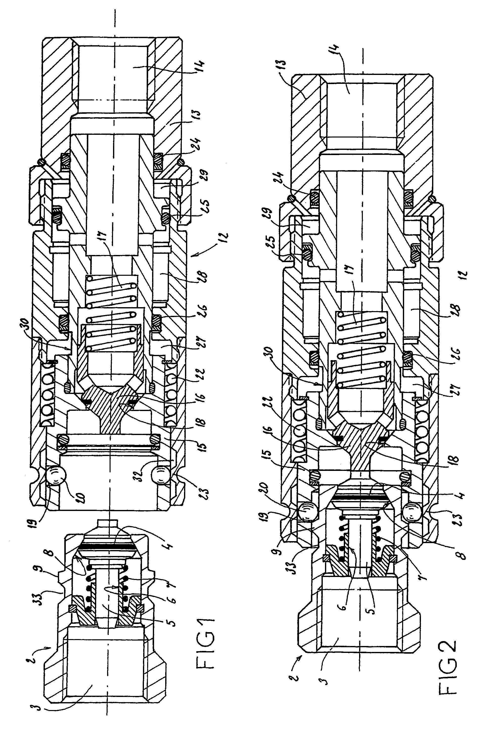
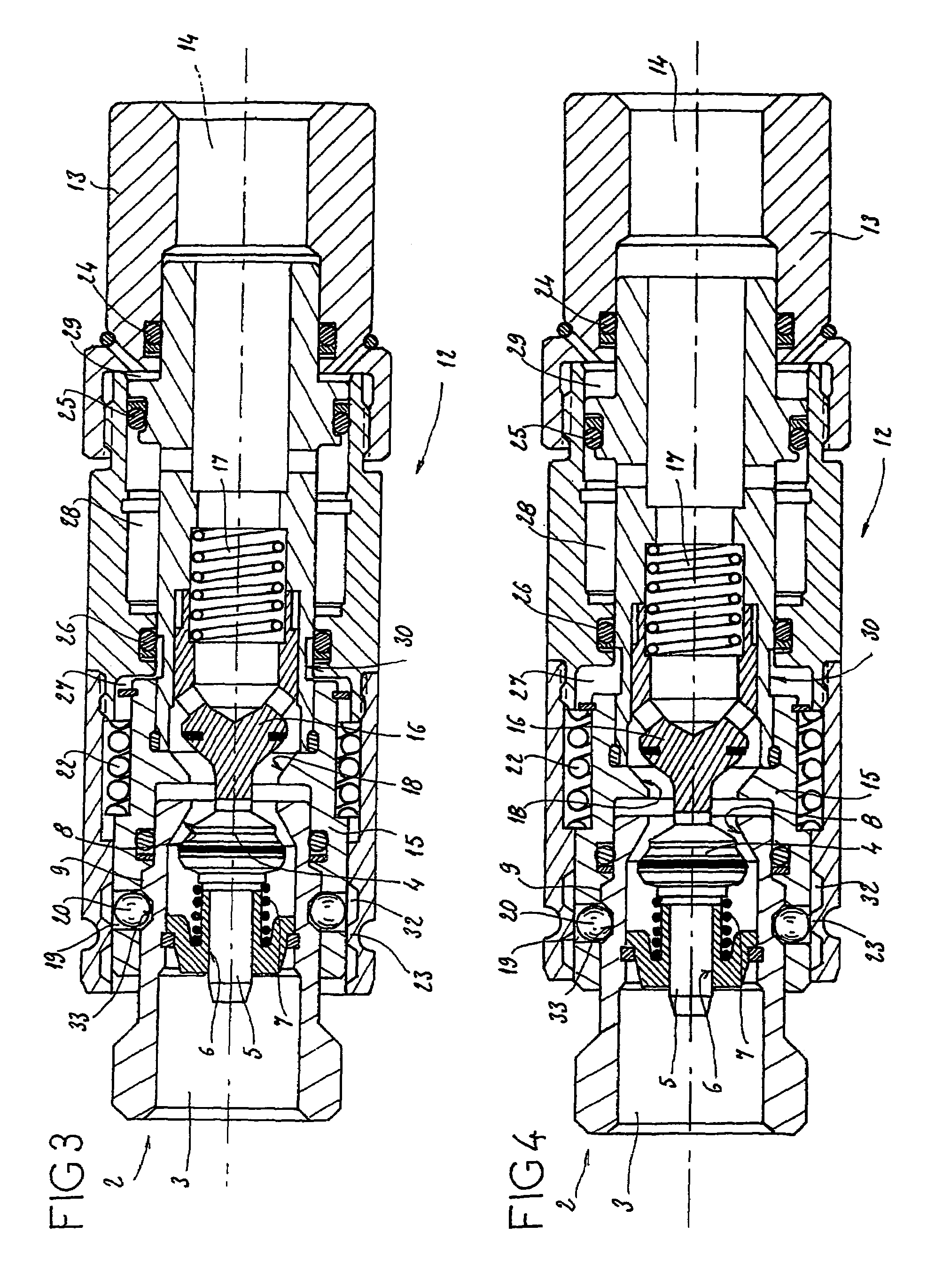
[0018]FIG. 1 represents the coupling in the uncoupled position.

[0019]This coupling comprises a male element 2 which can be fastened, for example to a flexible pipe, by screwing with the aid of a thread 3.

[0020]The male element 2 comprises, at its front end, a shut-off element 4 whose rear wall comprises a stem 5 slidably mounted in a cylinder 6 fastened in the male element. A spring 7 arranged between the lower part of the cylinder and the head of the shut-off member 4 normally keeps said head in a sealed closed position against a seat 8. The male element comprises an annular shoulder 9 in the vicinity of its front end.

[0021]This coupling also comprises a female element 12 formed by an outer tubular part 13 whose rear end has a thread 14 for mounting it on a pipe or on a receiver. A moving coupling part 15, which is able to slide in the outer part 13, is mounted inside the outer tubular part.

[0022]A shut-off member 16, subjected to the action of a spring 17 which keeps it pressed fl...


PUM


Abstract

The invention relates to a quick-connect coupling for hydraulic fluid conduits. The inventive coupling consists of a male element and a female element comprising an outer tubular part and a mobile coupling part. In addition, joints are provided between the tubular parts and define chambers. According to the invention, during the coupling phase, one hydraulically-pressurised chamber can be communicated with an atmospheric pressure chamber, using at least one longitudinal groove or similar element which is disposed in the tubular coupling part or in the outer tubular part.

Description

BACKGROUND OF THE INVENTION AND DESCRIPTION OF THE PRIOR ART[0001]The subject of the present invention is a quick coupling for hydraulic fluid pipes. Such a quick coupling for hydraulic fluid pipes is known particularly from document EP-0 847 511 in the name of the Applicant.[0002]Such a hydraulic coupling comprises, in a manner known per se, a male element and a female element whose ends which are to be connected are closed by valves, each valve comprising a shut-off member which comes into bearing contact with the shut-off member of the other valve upon connection, each shut-off member being pressed elastically against a seat in the open position of the coupling, the female element comprising an outer tubular part fastened to the end of a pipe or to a hydraulic receiver and inside which is slidably mounted a tubular coupling part for coupling the male part, which itself contains a valve, the tubular coupling part being slidably mounted in the outer part, in an insertion direction,...

Claims


Application Information

Patent Timeline
Patent Type & Authority Patents(United States)
IPC IPC(8): F16L37/35F16L37/32
CPCF16L37/35Y10T137/87957Y10T137/87965
Inventor GIAGNOLI, SYLVAINROLLI, RICHARD
Owner PARKER HANNIFIN PAK
Why Eureka
Try Eureka