

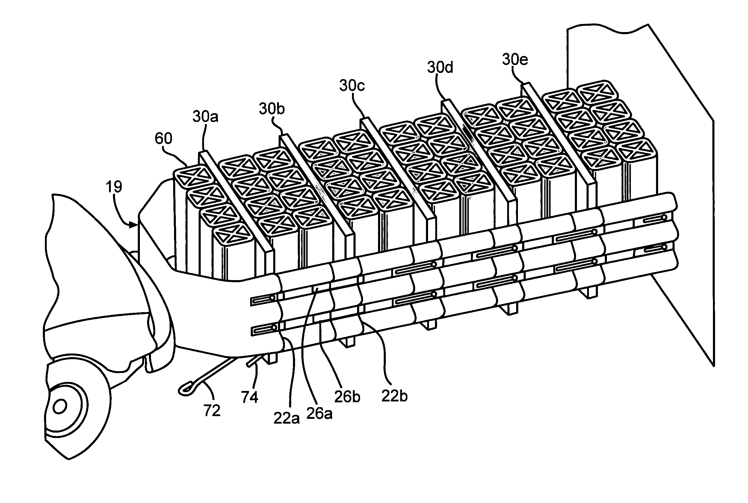
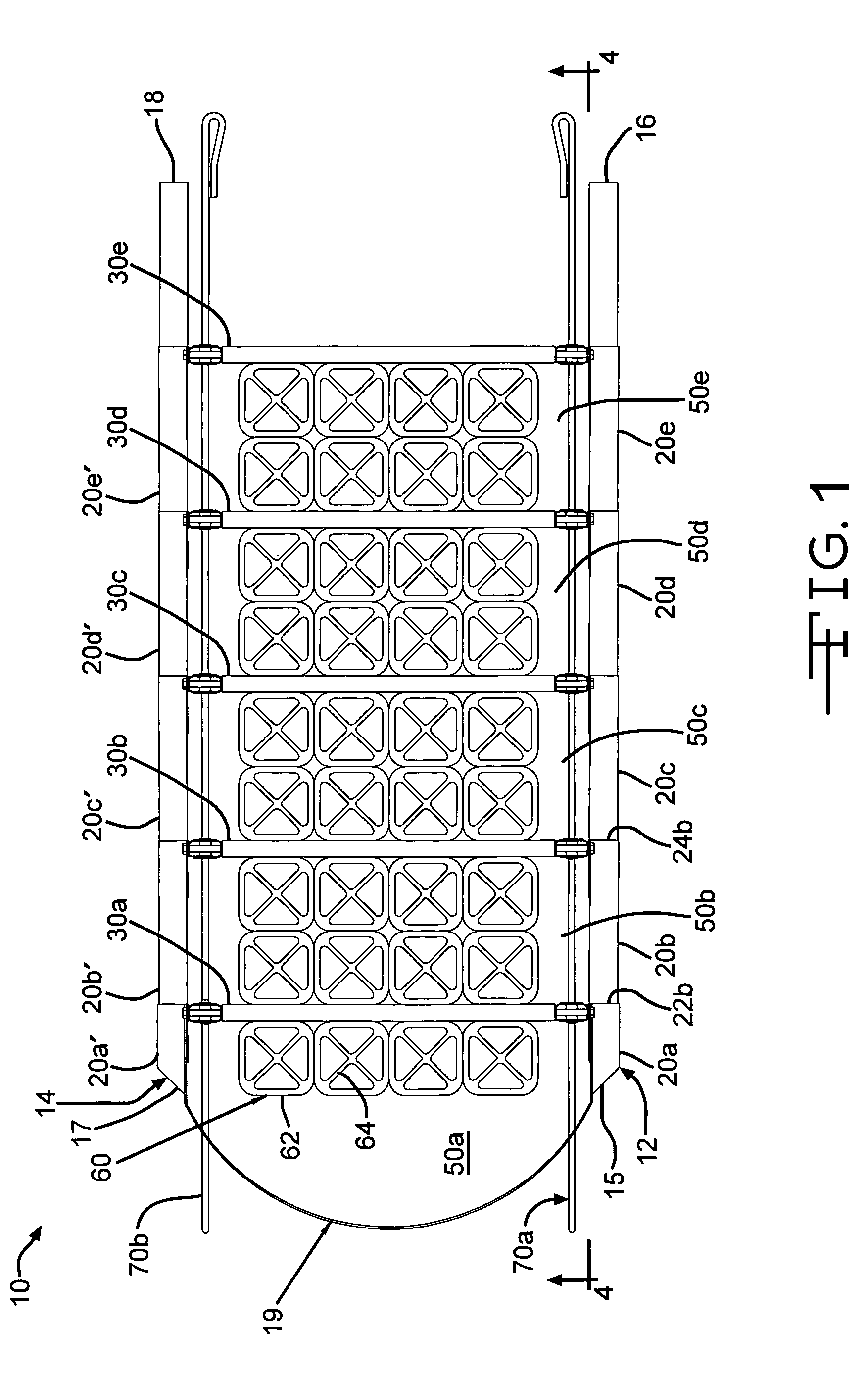
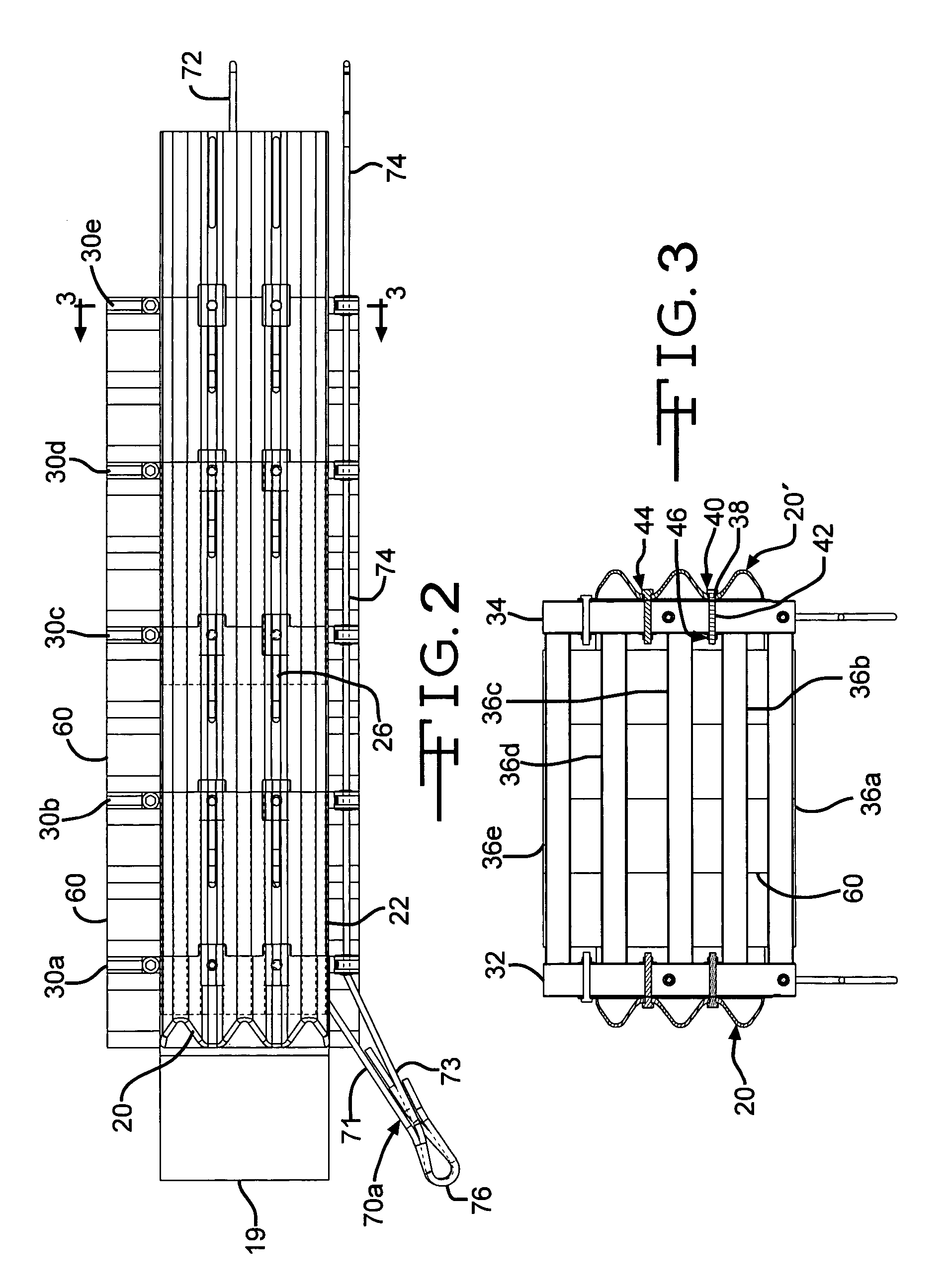
Impact attenuator system
a technology of attenuator and impact, which is applied in the direction of shock absorbers, traffic signals, roads, etc., can solve the problems of vehicle itself being crushed and bearing the brunt of impact, types of devices being damaged or destroyed, and reversing back onto the highway, etc., to achieve the desired level of reactivity, sufficient pouring time, and sufficient processing time
- Summary
- Abstract
- Description
- Claims
- Application Information
AI Technical Summary
Benefits of technology
Problems solved by technology
Method used
Image

Examples
example 1
Testing of the Hyperelastic Elements
[0099]A material for thermoset, cast polyurethane components for use in making the hyperelastic elements in the impact attenuator system was formulated. The material had a Young's modulus of at least about 4000 to about 6000 psi and provided optimized tensile and elongation properties at this stiffness. Samples were prepared from a formulation having the following physical properties: Young's modulus: 5933 psi; Tensile strength: 6830 psi; and Elongation: 638%.
[0100]The samples were submitted for hyper-elastic testing. As seen in the FIGS. 15, 16 and 17, the test results proved satisfactory. FIG. 15 is a graph showing the low-strain summary of hyperelastic mechanical properties at 23 C. FIG. 16 is a graph showing the mid-strain summary of hyperelastic mechanical properties at 23 C. FIG. 17 is a graph showing the high-strain summary of hyperelastic mechanical properties at 23 C.
[0101]Further large scale testing of an impact system incorporating the ...
example 2
Composition of the Hyperelastic Material
[0105]The hyperelastic material of the present invention was prepared using an MDI-polyester prepolymer having a free isocyanate content of approximately 19%. A separate long chain polyester component based on ethylene / butylene adipate was utilized. The polyol had an OH# of approximately 56. The short-chain diol utilized was 1,4-butanediol and accounted for approximately 18% by weight of the total hydroxyl-containing components of the mixture.
[0106]Reactive components were combined in a proportion that provided approximately 5% excess of isocyanate groups in the total mixture. A catalyst package was utilized which facilitated the chemical reaction of the components and allowed demold of the parts within a reasonable time frame. The gel time or work life of the system should not be shorter than the mold filling time to ensure uniform material properties throughout all sections of the part. The catalyst system contained a blend of a tertiary ami...
example 3
Process for Making Hyperelastic Material
[0108]A three component liquid casting machine equipped with a precision gear pump to accurately meter components and a dynamic mix head to obtain adequate mix quality and heating capability were used. The prepolymer, polyol and short-chain diol reactive components were charged into holding tanks heated to approximately 110° F. Approximate amounts of the catalyst components were added to the tank containing the short chain diol and mixed thoroughly. All components were then degassed under a minimum vacuum of 28 inches Hg until all dissolved gasses were removed. A dry nitrogen pad was then applied to each tank to protect components from moisture exposure. Pad pressure must be adequate to ensure material feed to a suction side of a metering pump. Each pump was calibrated to ensure delivery of an appropriate amount of the respective component to the mix chamber. The total material throughput was approximately 16.5 pounds per minute. A mold was he...
PUM
| Property | Measurement | Unit |
|---|---|---|
| elongation at break | aaaaa | aaaaa |
| tensile stresses | aaaaa | aaaaa |
| height | aaaaa | aaaaa |
Abstract
Description
Claims
Application Information