Hydraulic Vehicle Incorporating Efficient Energy Storage And Regeneration System

Active Publication Date: 2017-10-12
ENERGY SPRING LTD
View PDF2 Cites 5 Cited by
  • Summary
  • Abstract
  • Description
  • Claims
  • Application Information

AI Technical Summary

Benefits of technology

[0008]There is thus provided in accordance with the invention, a hydraulic energy powered vehicle, comprising a frame, an engine mounted on the frame and operative to supply a source of mechanical energy, a hydraulic pump coupled to the source of mechanical energy, the hydraulic pump operative to convert mechanical energy output from the engine to hydraulic energy at an output thereof, an accumulator array including one or more accumulator tanks, the accumulator array coupled to the output of the hydraulic pump, the accumulator array operative to store the hydraulic energy generated by the hydraulic pump in the one or more accumulator tanks, a hydraulic motor coupled to the accumulator array and operative to convert hydraulic energy released from the accumulator array into mechanical energy, a floating accumulator coupled to the hydraulic motor, a control system coupled to the accumulator array and the floating accumulator, the control system operative to coordinate the storage and release of hydraulic energy into and out of the one or more individual accumulator tanks of the accumulator array in accordance with throttle commands from a driver, and wherein the control system is operative to control the charging and discharging of hydraulic fluid into and out of the floating accumulator such that the pressure differential across the hydraulic motor is maintained at a desired level in accordance with the throttle commands.
[0009]There is also provided in accordance with the invention, a hydraulic energy powered vehicle, comprising at least one engine operative to supply a source of mechanical energy, a hydraulic pump coupled to the source of mechanical energy, the hydraulic pump operative to convert mechanical energy output from the engine to hydraulic energy at an output thereof, an accumulator array including a plurality of accumulator tanks, the accumulator array coupled to the output of the hydraulic pump, the accumulator array operative to store the hydraulic energy generated by the hydraulic pump in the plurality of accumulator tanks, one or more power units coupled to the accumulator array and operative to convert hydraulic energy released from the accumulator array

Problems solved by technology

Along with the growth of renewable energy sources is the problem of matching energy generation with energy consumption and demand.
For example, wind turbines only generate power

Method used


Image

  • Hydraulic Vehicle Incorporating Efficient Energy Storage And Regeneration System
  • Hydraulic Vehicle Incorporating Efficient Energy Storage And Regeneration System
  • Hydraulic Vehicle Incorporating Efficient Energy Storage And Regeneration System

Examples


Embodiment Construction

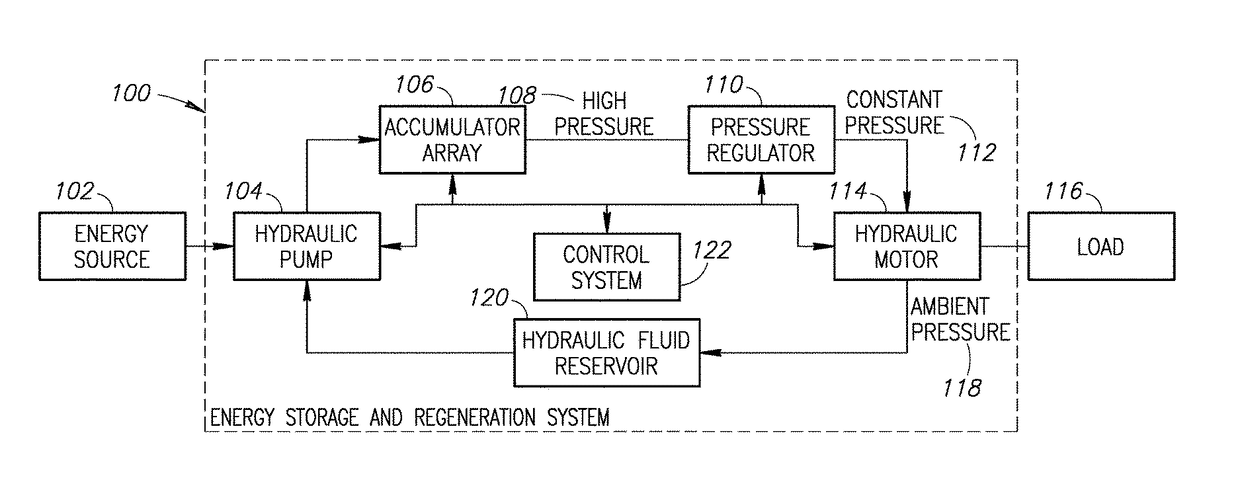
[0037]In the following detailed description, numerous specific details are set forth in order to provide a thorough understanding of the invention. It will be understood by those skilled in the art, however, that the present invention may be practiced without these specific details. In other instances, well-known methods, procedures, and components have not been described in detail so as not to obscure the present invention.

[0038]Among those benefits and improvements that have been disclosed, other objects and advantages of this invention will become apparent from the following description taken in conjunction with the accompanying figures. Detailed embodiments of the present invention are disclosed herein; however, it is to be understood that the disclosed embodiments are merely illustrative of the invention that may be embodied in various forms. In addition, each of the examples given in connection with the various embodiments of the invention which are intended to be illustrative...


PUM


Abstract

An energy storage and regeneration system that converts irregular, non-constant, and variable input power to regular, constant, and controlled output power using hydraulics whereby the irregular input power is used to pump hydraulic fluid into an accumulator array where it is stored pressurized. Energy is released in a controlled fashion using a hydraulic motor operated by the pressurized hydraulic fluid from the accumulator array, in accordance with the specified power demand. One or more power units may be deployed depending on the amount of energy required at the output. Each power unit includes a hydraulic motor and associated floating accumulator whose internal pressure is controlled to maintain a substantially constant pressure differential across its associated motor. The system can be integrated into various energy system sources including renewable energy such as wind, PV or thermal solar, wave, tidal, etc. as well as various types of vehicles such as cars, trucks, motorcycles, trains, boats, etc.

Description

REFERENCE TO PRIORITY APPLICATIONS[0001]This application is a continuation in part of U.S. application Ser. No. 13 / 641,277, filed Nov. 29, 2012, entitled “Hydraulic Power Converter,” which is a 371 of PCT / IB2011 / 051831, filed Apr. 27, 2011, entitled “Hydraulic Power Converter,” which claims priority to U.S. Provisional Application Ser. No. 61 / 328,746, filed Apr. 28, 2010, entitled “Novel System for Efficient Improvement in Hybrid Vehicles,” all of which are incorporated herein by reference in their entirety.FIELD OF THE DISCLOSURE[0002]The subject matter disclosed herein relates to the field of hydraulics and more particularly relates to vehicles incorporating an efficient system for storing and regenerating energy using hydraulics.BACKGROUND OF THE INVENTION[0003]Currently, the world is witnessing huge growth and development of renewable energy sources such as wind power, solar photovoltaics (PV) and thermal power, hydropower, wave and tidal power, etc. Along with the growth of ren...

Claims


Application Information

Patent Timeline
IPC IPC(8): F15B11/02F15B11/08B60K6/12F15B1/02F15B1/10
CPCF15B11/02F15B1/024F15B1/10F15B2211/20523F15B11/08F15B2201/3152B60K6/12F16H61/4096F16H61/44Y02T10/62B60W10/103B60W2710/24
Inventor BAUER, ABRAHAMWEISS, YONAFRUEHLING, YORAM
Owner ENERGY SPRING LTD
Why Eureka
Try Eureka