Improvements in and relating to sensitivity time control for radars

a radar and sensitivity time technology, applied in the field of sensitivity time control, can solve the problems of requiring transmission power, real risk of missing targets of interest, and low power of the received signal,

Inactive Publication Date: 2016-02-25
BAE SYSTEMS PLC
View PDF4 Cites 6 Cited by
  • Summary
  • Abstract
  • Description
  • Claims
  • Application Information

AI Technical Summary

Benefits of technology

[0016]According to a third aspect of the present invention, there is provided a Radar receiver operable to selectively attenuate a received signal, comprising: an attenuator arranged to selectively attenuate an input signal derived from an antenna; a receiver; a signal reconstructor, arranged to receive signals from the receiver and which is operable to boost the received signals by an amount equal to the level of attenuation provide by the attenuator; a sweep analyser, operable to identify a received signal which would place the receiver into saturation, were attenuation not applied by the attenuator; and an attenuation controller, operable to receive information from the sweep analysed on a received signal which would place the receiver into saturation and to control the attenuator to provide a desired level of attenuation.

Problems solved by technology

A relatively high transmit power is required to illuminate distant and / or small targets, but the power of the signal which is received can be very low indeed.
This poses a problem in that the receiver can be driven into saturation by the large return from the nearby object, simply because it must be very sensitive in order to successfully receive a return from a remote object.
However, this has the unwanted effect of adversely affecting its ability to receive weaker signals and poses a real risk that targets of interest may be missed as a result of desensitising the Radar receiver.
STC is necessary to ensure that the Radar is able to operate properly over a desired range, but prior art STC methods tend to be rather crude and apply one rule to all scenarios, which can unnecessarily degrade receiver performance, making it difficult to detect very small targets where desensitisation is being applied.
The application of desensitisation has an adverse effect on the ability to detect small targets at close range or, in the ambiguous case, larger targets at distant ranges.

Method used


Image

  • Improvements in and relating to sensitivity time control for radars
  • Improvements in and relating to sensitivity time control for radars
  • Improvements in and relating to sensitivity time control for radars

Examples


Embodiment Construction

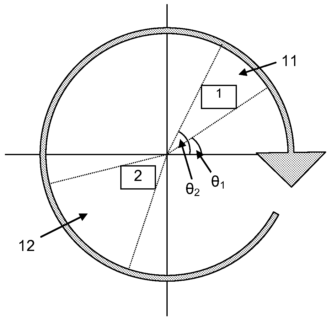
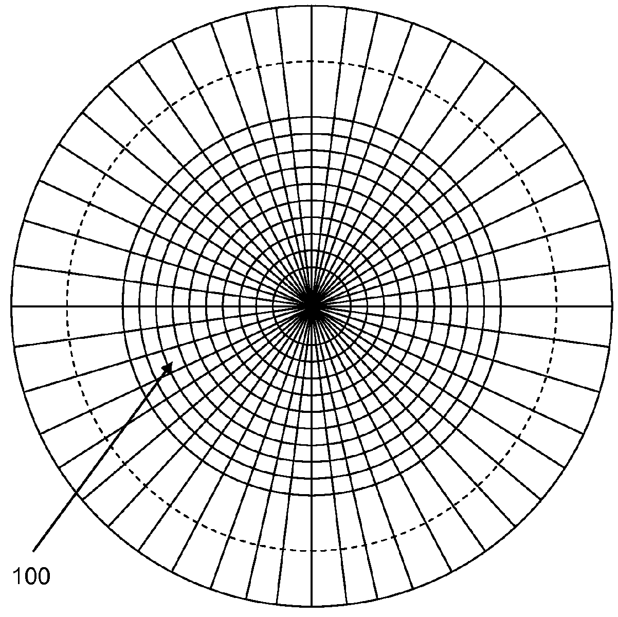
[0022]Embodiments of the invention seek to selectively desensitise the Radar receiver by applying different degrees of desensitisation (or attenuation) for different parts of the sweep. The different parts of the sweep may be different azimuthal sectors, different ranges (distance) or both.

[0023]In Radars fitted to ocean-going vessels, the problem of nearby clutter is not normally so great once the vessel is out in open water. The problem tends to be most pronounced in the littoral zone i.e. near the coast, where there are likely to be more objects nearby which can return a relatively strong signal.

[0024]However, in open water, a vessel may be travelling with one or more other vessels, for instance, and the return received from said one or more other vessels would be far greater than wanted returns from possible threats further afield. If the STC were adjusted for the entire azimuthal sweep (i.e. 360°), then the resulting desensitisation of the Radar receiver could result in wanted ...


PUM


Abstract

Disclosed is a method of providing selective attenuation in a Radar receiver, comprising the steps of: receiving a plurality of returns; identifying in a first scan, a return of a magnitude exceeding a predetermined threshold; applying in a subsequent scan, a predetermined desensitisation profile to said return. Also disclosed is a Radar receiver arranged to perform the method.

Description

FIELD[0001]The present invention is concerned with Sensitivity Time Control (STC), which is used in Radar systems to attenuate the very strong returns received from nearby targets, often clutter, which would otherwise drive the receiver into saturation.BACKGROUND TO THE PRESENT INVENTION[0002]Returns from any object tend to follow a 1 / R4 relationship. This arises because the power reaching the target decays at 1 / R2 on the way to the target and then decays at the same rate (1 / R2) on the way back to the Radar. The requirement to detect targets over extended range intervals, covering both near and far, places onerous design requirements on the Radar receiver. The receiver must operate over a very wide dynamic range in order to gave the ability to detect both large and small targets at both near and far ranges. A relatively high transmit power is required to illuminate distant and / or small targets, but the power of the signal which is received can be very low indeed.[0003]Objects near t...

Claims


Application Information

Patent Timeline
Patent Type & Authority Applications(United States)
IPC IPC(8): G01S7/34
CPCG01S7/34
Inventor BARROW, IAN
Owner BAE SYSTEMS PLC
Why Eureka
Try Eureka