Fiber optic mode scrambler and a method of manufacturing thereof

Active Publication Date: 2015-03-26
ROFIN SINAR LASER
View PDF8 Cites 6 Cited by
  • Summary
  • Abstract
  • Description
  • Claims
  • Application Information

AI Technical Summary

Benefits of technology

[0018]An advantage of the invention is that neither the non-adiabatic narrowings nor controlled bending cause significant power losses but only power redistribution among the optical modes provided that suitable parameters for the fiber are used. Typically the power losses are less than 1%.
[0019]The invention is also suited for fibers designed to carry high power levels from tens of Watts to several kilowatts.
[0020]Preferable embodiments are the subject of the dependent claims.
[0021]According to one embodiment the at least one non-adiabatic shape-change zone comprises a narrowing. Preferably, there are two or more, for example three, successive narrowings, which together with each other and the bending of the fiber cause the desired level of mode-scrambling.
[0022]Preferably, the bending region and the shape-change zone overlap. In other words, the shape-change zone, in particular the narrowing(s) are located at the bending

Problems solved by technology

However, high brilliance lasers may also give rise to new problems that are not encountered with sources having lower brilliance.
A particular problem arises in optics, such as beam collimating and focusing lenses that are used at the output of the laser source to condition the beam for a practical application.
Thermal lensing may cause distortions to the output beam, such as power dependent spot size and focal depth variations.
Such distortions sometimes make it difficult to control the particular application that the laser is being used for.
One practical example of problems relating to thermal lensing relates to upgrading existing laser sources with new ones.
As a manufacturer that uses the laser for an industrial application may exchange an older generation laser source to a higher brilliance new generation laser source, thermal lensing may become a serious issue.
So

Method used


Image

  • Fiber optic mode scrambler and a method of manufacturing thereof
  • Fiber optic mode scrambler and a method of manufacturing thereof
  • Fiber optic mode scrambler and a method of manufacturing thereof

Examples


Example

Definitions

[0037]The term “multi-mode optical fiber” refers to an optical fiber capable of carrying simultaneously a plurality of optical modes to be at least partially scrambled by means of the invention. Thus, the multi-mode fiber is understood here in the conventional sense of having a core that supports multiple optical modes. In typical end-user applications, the multi-mode optical fiber according to the invention is coupled to a multi-mode optical source, such as a fiber-laser source. The number of modes guided by a core of a multi-mode fiber can be hundreds. The best performance for the mode scrambler component of the invention is achieved with fibers having a strongly multi-mode character, where the optical mode spacing in propagation constant space is relatively dense, preferably less than 1000 m−1.

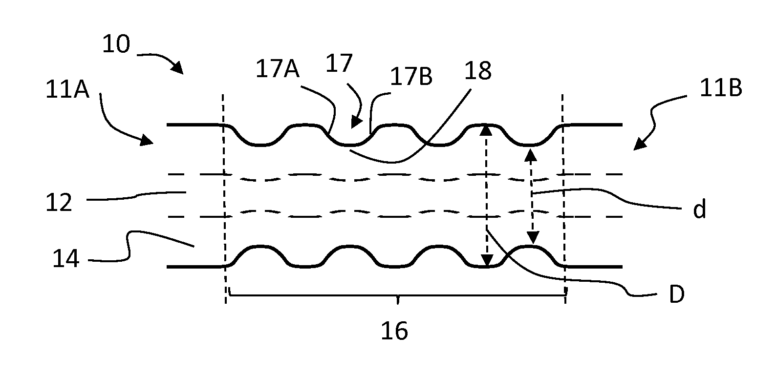
[0038]A “narrowing” means the combination of two tapers in the optical fiber, namely a down-taper gradually (over a down-taper length) reducing the diameter of the fiber from the...


PUM

PropertyMeasurementUnit
Fractionaaaaaaaaaa
Angleaaaaaaaaaa
Angleaaaaaaaaaa

Abstract

A fiber optic mode scrambler includes a multi-mode optical fiber formed with a core and a cladding around the core and a non-adiabatic cross-sectional shape change zone in the optical fiber. The fiber further has a bending region extending over a length of the optical fiber. The optical fiber has a non-zero curvature at the bending region and a device for maintaining the curvature of the optical fiber at the bending region. Mode scramblers can be provided that are accurately adjusted to match with different desired optical characteristics. A well-controlled manufacturing method for the mode scrambler is also described.

Description

FIELD OF THE INVENTION[0001]The invention relates to fiber optics, in particular a fiber-optic mode scrambler. The invention also relates to a method of mixing or scrambling optical modes in multi-mode optical fibers. The invention can be used e.g. in connection with fiber-delivered high power laser sources, such as fiber lasers.BACKGROUND OF THE INVENTION[0002]Present day high power laser sources exhibit high quality beams with very high brilliance in the multi-kW power range. For instance, commercial fiber lasers are available with single-mode power of 1 kW and above. Using such high brilliance laser sources in practical applications offers various benefits compared to older generation sources with lower beam quality, such as larger focusing depth and smaller spot size.[0003]However, high brilliance lasers may also give rise to new problems that are not encountered with sources having lower brilliance. A particular problem arises in optics, such as beam collimating and focusing le...

Claims


Application Information

Patent Timeline
IPC IPC(8): G02B6/26G02B6/10
CPCG02B6/102G02B6/268G02B6/02066G02B6/14G02B6/2552G02B6/4296G02B27/0994H01S3/005G02B6/02023G02B6/1228G02B6/125G02B27/0927G02B6/02057
Inventor SALOKATVE, ARTONAPPI, JARI
Owner ROFIN SINAR LASER
Why Eureka
Try Eureka