
A millimeter-wave ferrite switch matrix in the form of an all-waveguide

A technology of switch matrix and ferrite, which is applied in the direction of waveguide devices, circuits, electrical components, etc., can solve the problems of large loss, large loss, and low power resistance level of switching units, and achieve increased gain, reduced loss, and high buff effect

Active Publication Date: 2019-01-15
CHINA ELECTRONIC TECH GRP CORP NO 38 RES INST
View PDF10 Cites 0 Cited by
  • Summary
  • Abstract
  • Description
  • Claims
  • Application Information

AI Technical Summary

Problems solved by technology

The waveguide antenna in the millimeter wave band has the advantages of low loss, high gain, and high power resistance, so the multi-beam antenna system in the millimeter wave band mostly adopts the waveguide antenna form. The switch matrix is ​​the main component of the waveguide multi-beam antenna system. Currently, the switch matrix uses Semiconductor switch unit, the disadvantages of this form of switch matrix are: 1. Low power resistance
The power resistance level of the switch matrix is ​​determined by the switch unit. At present, the power resistance of the semiconductor switch unit is only about 4W (average power), resulting in a low power resistance level of the waveguide multi-beam antenna system, which greatly limits the distance of wireless communication and the range of radar detection power; 2. The semiconductor switch unit in the millimeter wave band has a large loss, and the GaAsPIN switch unit with the smallest loss in the case of low power (average power less than 4W) also has about 0.8dB, and the loss caused by the microstrip-waveguide transition structure causes the loss of the entire switch matrix to be biased. Large, which reduces the gain of the antenna system and the range of detection power; 3. Complex structure, high processing cost, and large loss
The semiconductor switch unit is not in the form of a waveguide, and needs to go through a microstrip-waveguide conversion transition structure to connect with the waveguide system, resulting in an extremely complex structure of the entire switch matrix and increased processing costs

Method used


Image

  • A millimeter-wave ferrite switch matrix in the form of an all-waveguide
  • A millimeter-wave ferrite switch matrix in the form of an all-waveguide
  • A millimeter-wave ferrite switch matrix in the form of an all-waveguide

Examples


Embodiment 1

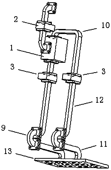
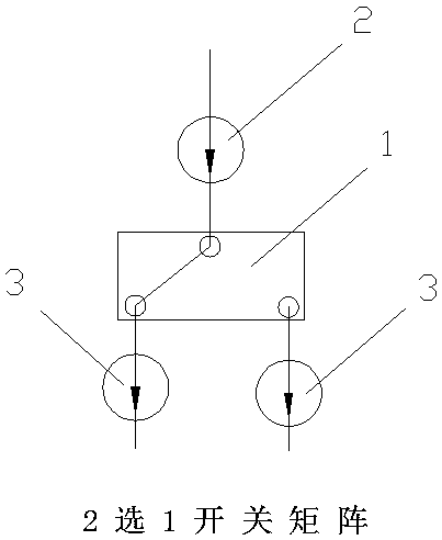
[0030] A millimeter-wave ferrite switch matrix in the form of a full waveguide can be used for the selection function of the two-to-one switch in the frequency range of 30-40GHz.

[0031] see figure 2 A millimeter-wave ferrite switch matrix in the form of a full waveguide includes a ferrite switch unit 1, and the ferrite switch unit 1 is a microwave ferrite device. The input end of the ferrite switch unit 1 is connected to the inlet isolator 2 through the waveguide, and the two output ends of the ferrite switch unit 1 are respectively connected to the outlet isolator 3 through the waveguide, forming an alternative switch matrix. The input terminal of the inlet isolator 2 is the horizontally polarized input terminal of the one-of-two switch matrix, and the output terminals of the two outlet isolators 3 are the horizontally polarized output terminals of the one-two switch matrix. The electromagnetic waves of one horizontally polarized input terminal and two horizontally polari...

Embodiment 2

[0036] A millimeter-wave ferrite switch matrix in the form of a full waveguide is used for the three-to-one switch selection function in the frequency range of 30-40GHz.

[0037] see Figure 4 , A three-choice switch matrix is ​​formed by connecting two two-one switch matrices; it has one vertically polarized input terminal and three horizontally polarized output terminals.

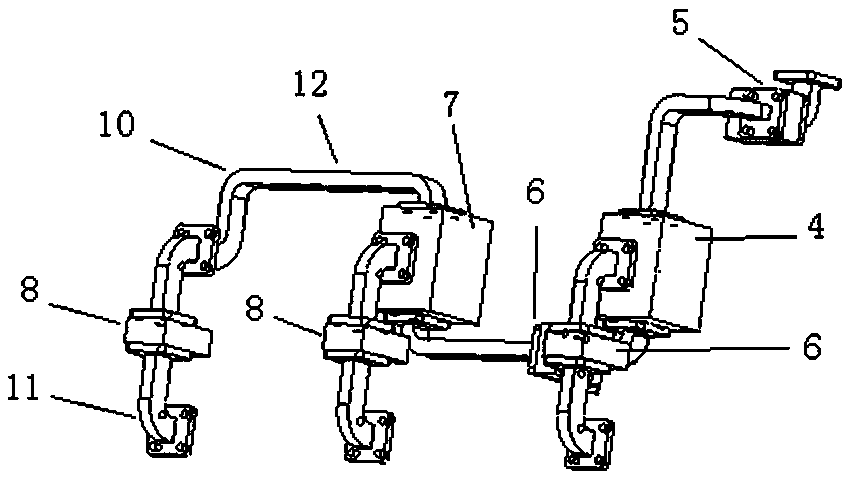
[0038] see image 3 , the specific structure: the input terminal of one alternative-two switch matrix is ​​connected with one output terminal of another alternative-two switch matrix to form a three-select one switch matrix, and the three horizontally polarized outlets are on the same plane. The electromagnetic wave arbitrary switching output of one vertically polarized input terminal and three horizontally polarized output terminals is realized.

[0039] at work, see image 3 The electromagnetic wave transmission path is: vertically polarized input terminal → E-bend waveguide → imported isolator 5 → H-b...

Embodiment 3

[0042] A millimeter-wave ferrite switch matrix in the form of a full waveguide is used for the six-to-one switch selection function in the frequency range of 30-40GHz.

[0043] see Figure 6 , a six-to-one switch matrix is ​​formed by connecting and combining five two-to-one switch matrices, which has one vertically polarized input terminal and six horizontally polarized output terminals. Realize one vertically polarized input terminal and six horizontally polarized output terminals of electromagnetic waves with equal amplitude and in-phase arbitrary switching output.

[0044] see Figure 5 , the specific structure: the input ends of the first two-to-one switch matrix and the second two-to-one switch matrix are respectively connected to the output terminals of the third two-to-one switch matrix; the input terminals of the third two-to-one switch matrix are connected to the fourth One output end of the one-two switch matrix; the other output end of the fourth one-two switch m...


PUM


Abstract

The present invention relates to a full-waveguide millimeter wave ferrite switching matrix. The full-waveguide millimeter wave ferrite switching matrix comprises a ferrite switching unit; the input end of the ferrite switching unit is provided with an inlet isolator through a waveguide, and the two output ends of the ferrite switching unit are respectively provided with an output isolator through a waveguide, and therefore, a one-out-two switching matrix can be formed; the input end of the inlet isolator is the horizontal polarization input end of the one-out-two switching matrix; the output ends of the two output isolators are the horizontal polarization output ends of the one-out-two switching matrix; and three or more one-out-two switching matrixes are combined to form a one-out-three switching matrix or one-out-n switching matrix, wherein n is larger than 3. Compared with a conventional semiconductor switching matrix, and according to the full-waveguide millimeter wave ferrite switching matrix of the invention, a microstrip-waveguide conversion transition structure is omitted, and therefore, the structure of the full-waveguide millimeter wave ferrite switching matrix is simper, and the processing cost of the full-waveguide millimeter wave ferrite switching matrix is lower, and the processing cost of the full-waveguide millimeter wave ferrite switching matrix is reduced by at least 20%; and the switching matrix has higher power withstanding level, and the average power of the full-waveguide millimeter wave ferrite switching matrix can achieve 15W, and the power withstanding level of the full-waveguide millimeter wave ferrite switching matrix is more than three times of that of the semiconductor switching unit, and the loss of the full-waveguide millimeter wave ferrite switching matrix is lower under same power.

Description

technical field [0001] The invention belongs to the technical field of waveguide multi-beam antennas for millimeter-wave radar and communication systems, and specifically relates to a waveguide mainly composed of a ferrite switch unit, an isolator, a U-shaped waveguide, and some straight waveguides, E-bend waveguides, H-bend waveguides, and twisted waveguides. and so on composed of ferrite switch matrix. Background technique [0002] Multi-beam antenna can use a single antenna to form multiple beams in different directions. In addition to effectively reducing the volume and cost, it can also achieve wide-angle coverage. It is a key technology in wireless communication and modern radar, and has a wide range of applications. application prospects. The waveguide antenna in the millimeter wave band has the advantages of low loss, high gain, and high power resistance, so the multi-beam antenna system in the millimeter wave band mostly adopts the waveguide antenna form. The switc...

Claims


Application Information

Patent Timeline
Patent Type & Authority Patents(China)
IPC IPC(8): H01P1/11
CPCH01P1/11
Inventor 范宇赖清华
Owner CHINA ELECTRONIC TECH GRP CORP NO 38 RES INST
Learn More