
High-power laser amplifier head

Pending Publication Date: 2021-12-16
CENT NAT DE LA RECHERCHE SCI
View PDF0 Cites 0 Cited by
  • Summary
  • Abstract
  • Description
  • Claims
  • Application Information

AI Technical Summary

Benefits of technology

The invention is a new laser amplifier head that can cool down better than previous versions, allowing for higher power without compromising the quality of the laser beam.

Problems solved by technology

The combined use of a plurality of moving thin plates and cooling by liquid poses a particular difficulty: in fact, in the absence of particular precautions, the liquid flow tends to become turbulent, thereby substantially degrading the quality of the laser beam (article [8], for example, illustrates the effects of the turbulence in the case of a thin-disk laser oscillator without moving parts).

Method used


Image

  • High-power laser amplifier head
  • High-power laser amplifier head
  • High-power laser amplifier head

Examples


first embodiment

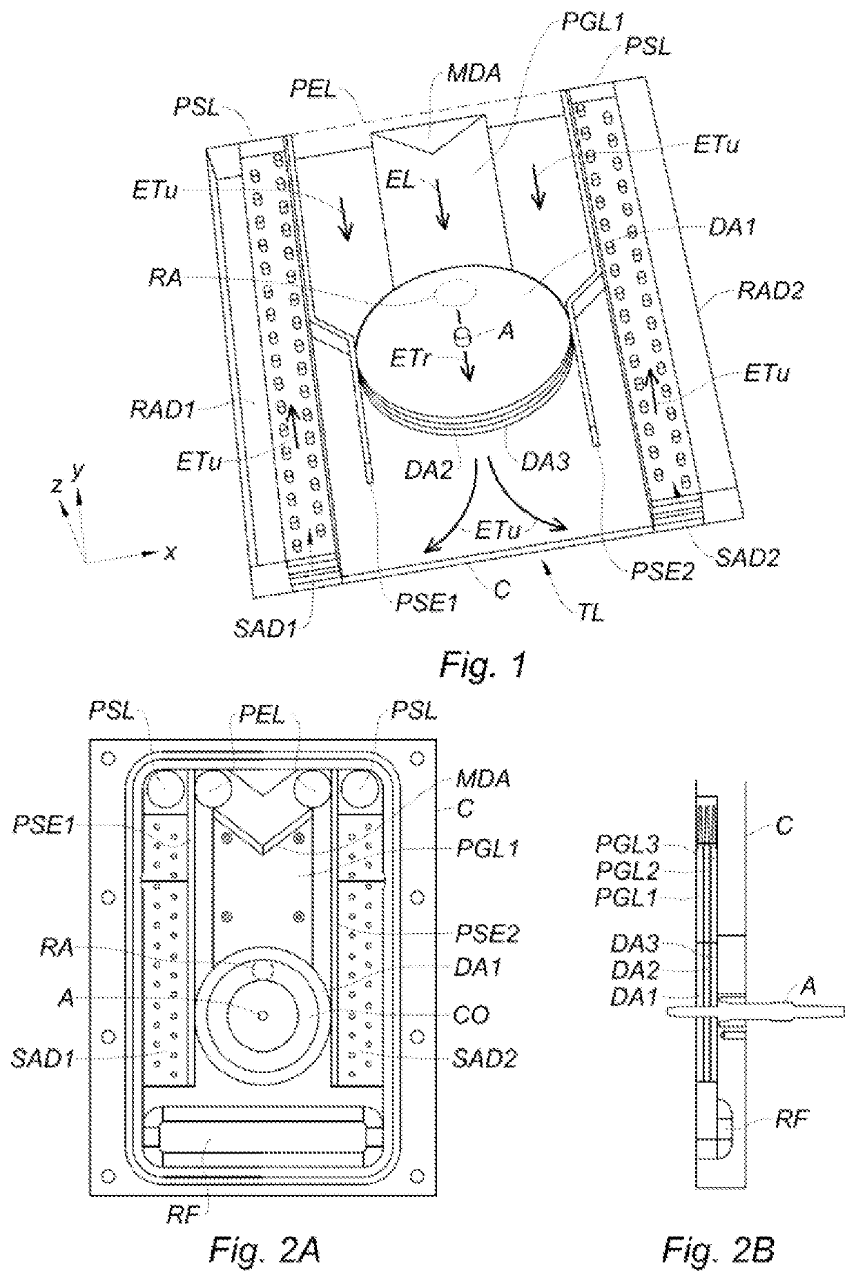
[0031]The cutaway view shown in FIG. 1 provides an understanding of the structure of a laser amplifier head according to the invention. The laser active medium is made up of three plates, more precisely disks, DA1, DA2, DA3 consisting of yttrium-aluminum-garnet (YAG) doped with ytterbium (Yb:YAG), having a thickness of 3 mm and a diameter of 70 mm, mounted in series on a tree A passing through their center, with a spacing between two adjacent disks of 500 μm. The tree A allows the disks to be rotated, for example at a speed of between 1 and 10 revolutions per second. The assembly is placed inside a parallelepiped-shaped housing C. The reference z denotes the orientation direction of the tree A, and the references x, y denote axes perpendicular to one another and to the axis z defining a plane parallel to the main surfaces of the disks.

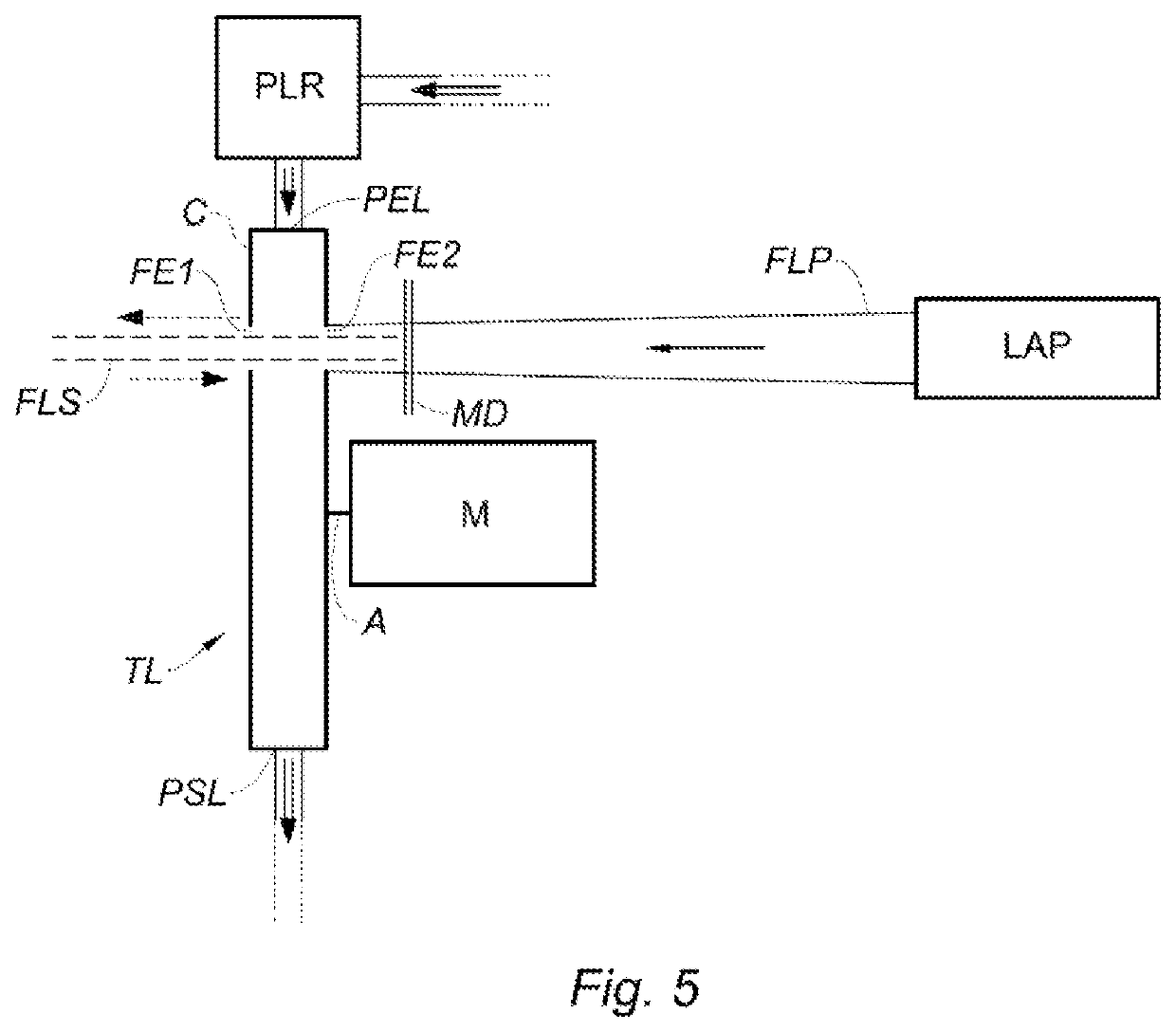
[0032]The laser beam to be amplified and the pump laser beam which enter and exit the housing via windows or porthole (see FIG. 5 for more details), p...

second embodiment

[0038]FIGS. 2A and 2B illustrate a second embodiment in which the walls PSE1, PSE2 are straight and parallel, such that the width of the central channel is throughout hardly greater than the diameter of the disks. A groove RF with rounded edges forming a hollow which creates a zone in which the flow can extend, and therefore slows down, can also be noted in the “low” part (opposite the liquid inlet and outlet ports), thus facilitating its ascent via the sides.

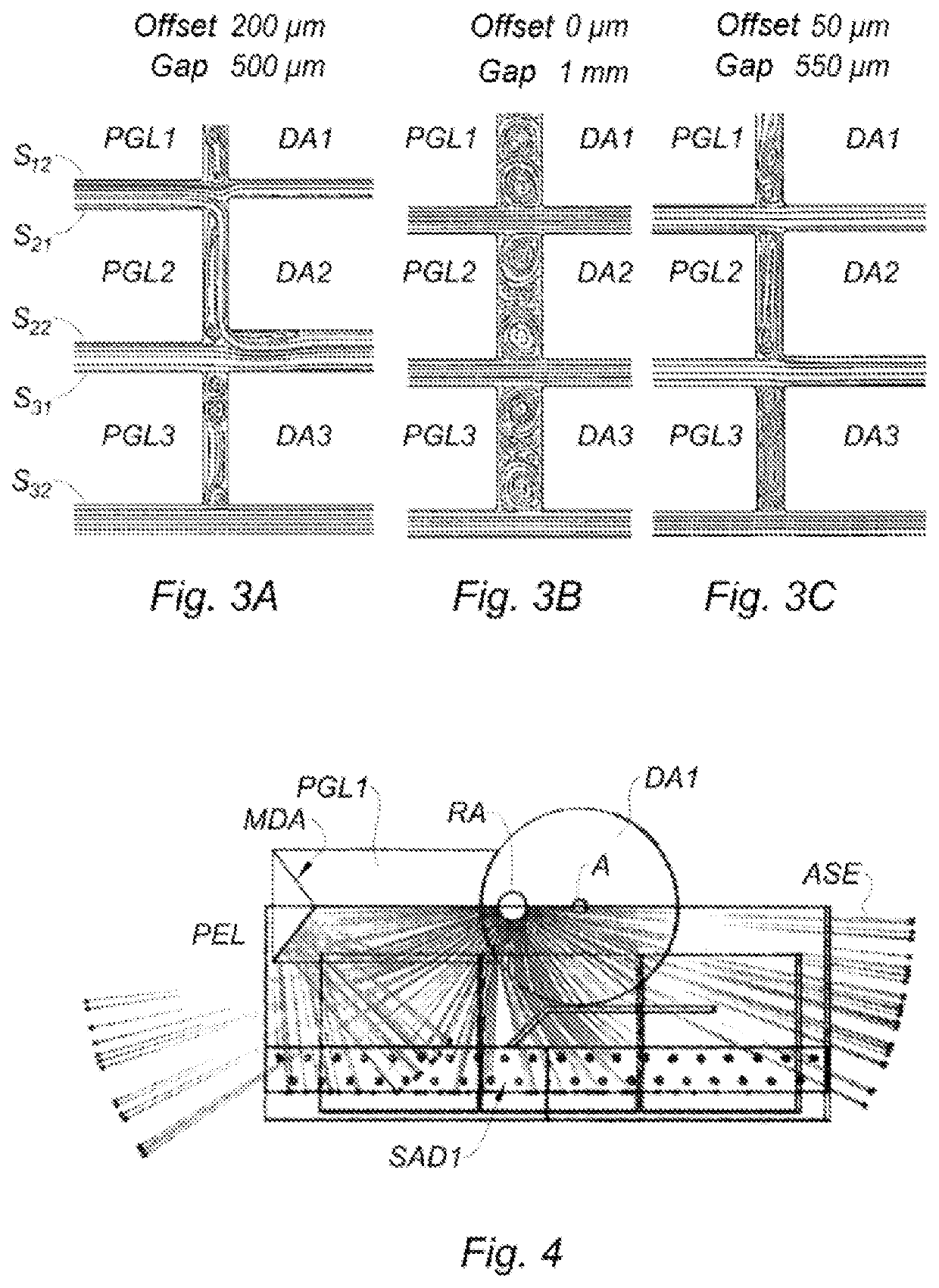
[0039]The plates PGL1-PGL3 which allow the shaping of the laminar water flow upstream of the disks are fixed, whereas the latter rotate. A gap therefore necessarily exists between these two types of components. Moreover, due to the inevitable mechanical tolerances, an offset will generally exist in the direction z between each liquid guide plate and the corresponding disk. 2D simulations of the flows have been created for three examples, illustrated by FIGS. 3A, 3B and 3C:

[0040]FIG. 3A: gap of 500 μm and offset of 200 μm;

[0041]...


PUM


Abstract

A laser amplifier head is provided. The laser amplifier head includes a plurality of plates of a solid-state laser active medium disposed in a housing, arranged parallel to one another with their main surfaces facing one another, the housing being provided with an inlet port and an outlet port for a cooling liquid, and also at least one window allowing a laser beam to pass through the laser active medium plates, wherein it also includes:a mechanical connection device allowing a cyclic movement at least of the laser active medium plates in relation to the laser beam in a plane (xy) perpendicular to the direction (z) of their thickness; andcooling liquid guide plates arranged in the extension of the laser active medium plates, between the latter and the inlet port of said liquid.

Description

CROSS-REFERENCE TO RELATED APPLICATIONS[0001]The present application is a national phase entry of PCT / EP2019 / 079111, filed on Oct. 24, 2019, which claims the benefit of priority of French Application No. 1860215, filed Nov. 6, 2018, the entire contents of which are hereby incorporated by reference in their entirety for all purposes.TECHNICAL FIELD[0002]The invention relates to a solid-state laser amplifier head which is intended to be used at high power (average power in the order of 1 kW or more, pulses in the order of 1 J or more). The laser head according to the invention is particularly suitable for the implementation of a laser amplifier, but can also be placed inside an optical cavity in order to implement an oscillator or a regenerative amplifier.BACKGROUND[0003]In the design of a solid-state laser, in particular intended to operate at high powers, the cooling of the active medium is particularly important. In fact, an excessive temperature adversely affects the amplification...

Claims


Application Information

Patent Timeline
IPC IPC(8): H01S5/04H01S5/024H01S5/02208
CPCH01S5/041H01S5/02208H01S5/02423H01S3/0401H01S3/0407H01S3/042H01S3/0604H01S3/07H01S3/1026H01S3/2316
Inventor FERAL, CHRISTOPHELHERMITE, JÉRÔMEBRANDAM, JÉRÉMYMARION, DENIS
Owner CENT NAT DE LA RECHERCHE SCI
Learn More