Method and apparatus for conversion of a pneumatic actuator to an electric power platform

Pending Publication Date: 2022-05-19
HYBRID AUTOMATION INC
View PDF18 Cites 0 Cited by
  • Summary
  • Abstract
  • Description
  • Claims
  • Application Information

AI Technical Summary

Benefits of technology

The patent describes a way to turn a pneumatic actuator into an electric actuator that can fail-safe. This is done by adding an electro-pneumatic device that works with any existing pneumatic actuator. The new device uses a closed pneumatic system, which increases efficiency and reduces power consumption. This is done by using the actuator as a fluid supply source to the compressor, which results in faster valve transitions and lower power consumption. Overall, this allows for better control and operation of the valves.

Problems solved by technology

Most electric actuators are dumb; meaning that in the event of power loss the actuator / valve fails in place, be it open, closed or somewhere between.
Currently, fail-safe electric actuator technology suffers from a wide range of issues, including but is not limited to, torque output, lack of system reliability, very large / heavy unit size for a given valve, limited cycling before requiring maintenance, etc.
If maintenance is not kept up with, such as the changing of air filters, which filter the air entering the system, this lack of maintenance can ripple through the system damaging components downstream.
Pneumatic systems that are routed through a network of pipes in large scale applications such as in power plants and refineries commonly fall victim to problems such as line leakage or downstream pressure loss.
In many of these applications, there are several hundred pipes and fittings routed throughout a location causing the maintenance and isolation of faulty pipes and fittings to be difficult.
Any leakage of generated compressed air is a direct cost to the entity utilizing such pneumatic systems.
Pneumatic systems routed through a network of pipes in large scale applications often suffer from the additional problems of responsiveness and repeatability due to their placement at large distances from their fluid (e.g., gas) supply source.
This lack of responsiveness and repeatability can cause unpredictable behavior in large pneumatic systems ranging from timing of valve transitions to lack of pressure at key placement points.
Pneumatic systems are generally known for the opposite; low levels of power efficiency, high levels of power density, and low levels of accurate repeatability and control.
This feature both reduces the minimum time between valve transitions and reduces the power drawn from the compressor—due to it having to overcome a smaller pressure differential during charge cycles.

Method used


Image

  • Method and apparatus for conversion of a pneumatic actuator to an electric power platform
  • Method and apparatus for conversion of a pneumatic actuator to an electric power platform
  • Method and apparatus for conversion of a pneumatic actuator to an electric power platform

Examples


Embodiment Construction

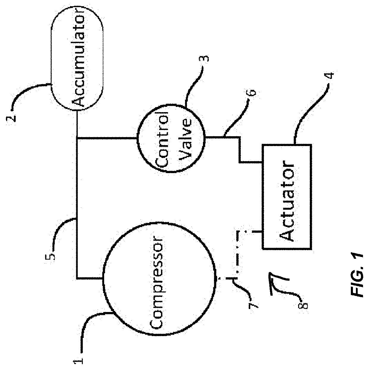
[0043]Referring to FIG. 1, depicted therein is one embodiment of the electric power actuator in its simplest form comprising a source of compressed gas (air) such as, for example compressor 1 and / or accumulator 2, connected to a control valve 3 by fluid line 5, and a fluid actuator 4 connected to control valve 3 by fluid line 6. Fluid line 7 is an optional fluid line that, when included, allows for closed system operation of the embodiment of the electric power actuator.

[0044]It should be understood that the various components in pneumatic circuits, such as those disclosed herein are generally interconnected by sealed fluid / gas lines, and such fluid / gas lines interface or connect to the components at ports existing in the components. The various connections, while possibly permanent connections, are likely threaded and compression-fit connections both between and to the components. Accordingly, when the disclosure indicates that components are connected, or more specifically fluidly...


PUM


Abstract

An electric-powered fail-safe actuator for use with a valve, where the actuator stores potential energy for conversion to kinetic energy to close or open the valve to the fail-safe position.

Description

[0001]This application is a continuation-in-part of, and claims priority under 35 U.S.C. § 120 from, co-pending application Ser. No. 16 / 999,635 for a METHOD AND APPARATUS FOR CONVERSION OF SINGLE-ACTING PNEUMATIC ACTUATOR TO ELECTRIC POWER PLATFORM, filed Aug. 21, 2020 by Robert Connal et al., which claimed priority under 35 U.S.C. § 119(e) to U.S. Provisional Patent Application No. 62 / 889,765, entitled CONVERSION OF SINGLE-ACTING PNEUMATIC ACTUATOR TO ELECTRIC POWER PLATFORM, filed Aug. 21, 2019 by Robert Connal et al., both of which are hereby incorporated by reference in their entirety.BACKGROUND AND SUMMARY[0002]The disclosed electric power actuators pertain generally to fluid flow control and, more particularly, to a pneumatic control system designed to operate and control various types of pneumatic actuators.[0003]As evidenced by the oil and gas industry, there is a need for better, more reliable, and fail-safe electric actuators. Most electric actuators are dumb; meaning that...

Claims


Application Information

Patent Timeline
IPC IPC(8): F15B9/03F15B21/041
CPCF15B9/03F15B21/041F15B2211/8752F15B20/002F15B11/064F15B2211/8855F15B2211/7052F15B2211/7053F15B2211/50554F15B2211/5151F15B2211/88F15B2211/3138F15B2211/327F15B2211/20538F15B2211/20515F15B2211/6309F15B2211/21F15B2211/6651F15B2211/6306F15B13/027F15B13/025
Inventor CONNAL, ROBERTFRASH, SCOTT
Owner HYBRID AUTOMATION INC
Why Eureka
Try Eureka