Wire termination device having test contacts on cover

a termination device and wire termination technology, applied in the field of wire termination devices, can solve problems such as insufficient room for testing ports to be disposed

Inactive Publication Date: 2007-01-30
CORNING OPTICAL COMM LLC
View PDF10 Cites 25 Cited by
  • Summary
  • Abstract
  • Description
  • Claims
  • Application Information

AI Technical Summary

Benefits of technology

[0007]The devices and methods of the present invention are advantageous. The test contacts are located within the cover of the PTD rather than the bridge. Thus, the cover of the PTD can be opened and closed without having to disconnect and reconnect the test probes from the test contacts. Further, the devices and methods of the invention are conducive to the use of IDCs since sufficient areas of the cover will be available for viewing windows and labeling to be placed thereon.

Problems solved by technology

The presence of the windows and the labeling on the cover leaves insufficient room for test ports to be disposed through the cover.

Method used


Image

  • Wire termination device having test contacts on cover
  • Wire termination device having test contacts on cover
  • Wire termination device having test contacts on cover

Examples


Embodiment Construction

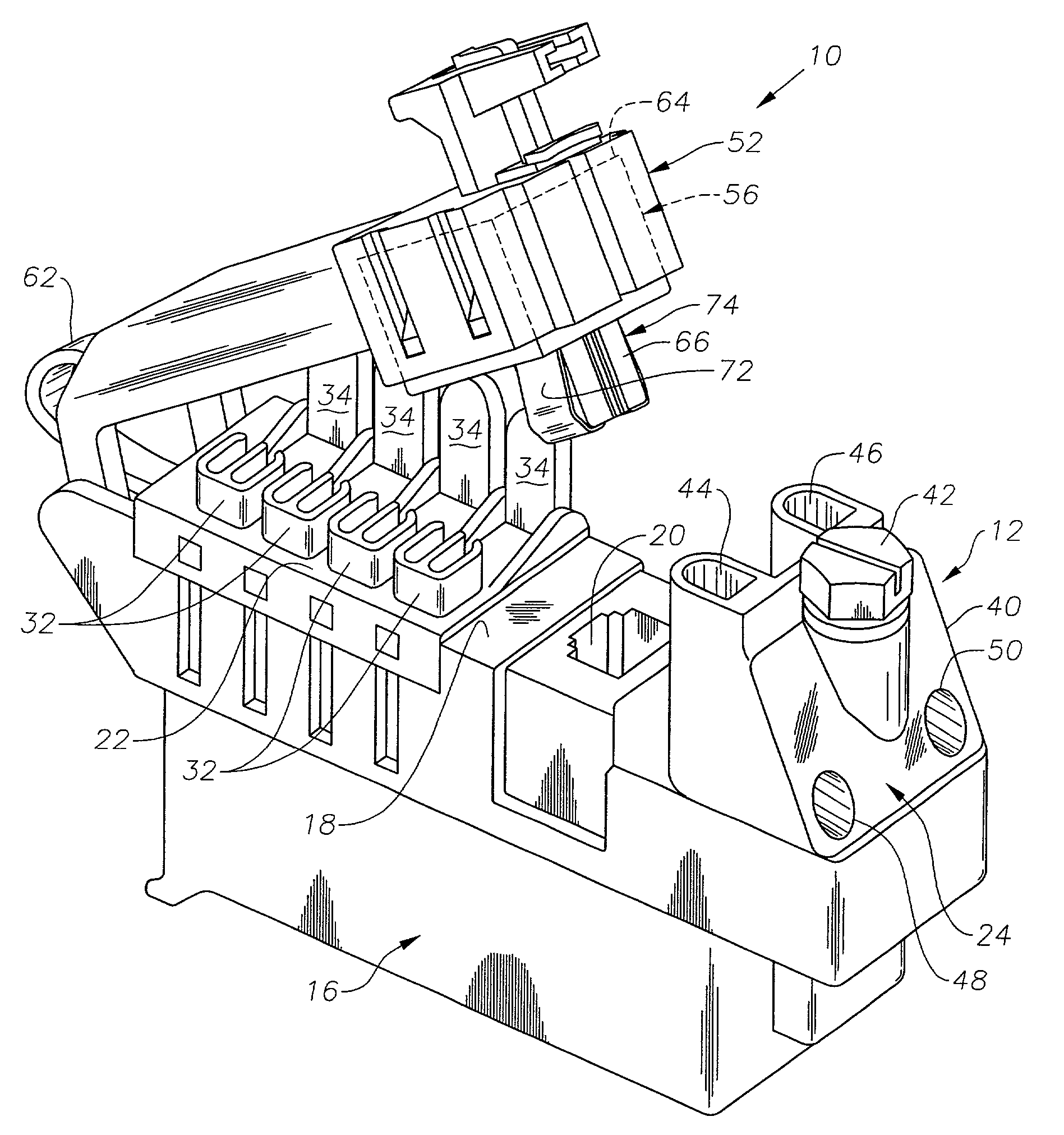
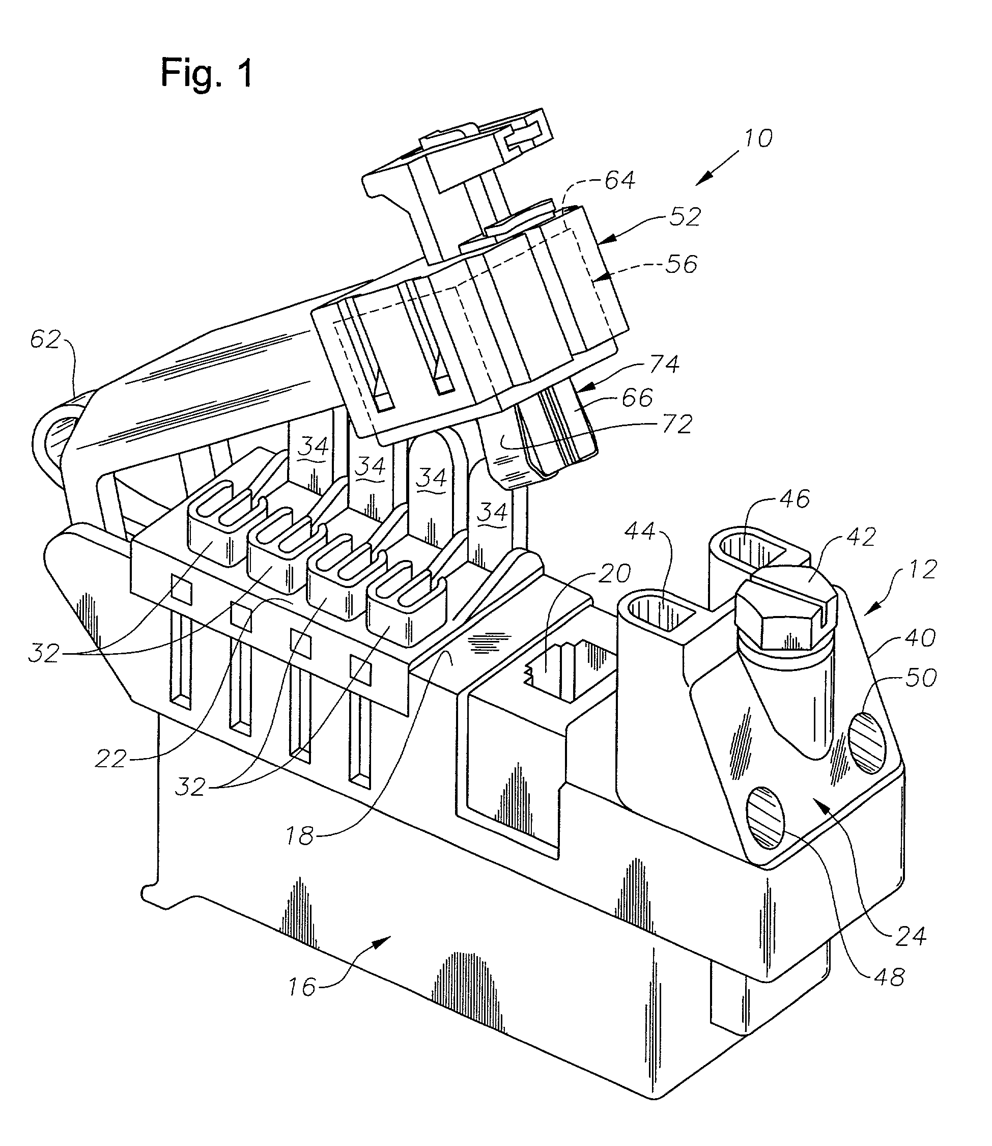
[0018]FIG. 1 shows an exemplary PTD 10 of the type used within a NID. The PTD 10 includes a base 12 and a cover 14 that is hingedly affixed to the base 12. During use, the PTD 10 is typically disposed inside the compartment of a NID (not shown) along with a number of other PTDs of the same construction. The construction and operation of typical NIDs is well understood by those of skill in the art, and therefore, will not be described in further detail herein. It should be understood, however, that the invention has application to variants of wire termination devices other than standard telephone PTDs. Examples include flood-rated termination modules and line modules.

[0019]The base 12 of the PTD 10 contains a lower compartment, generally indicated at 16, and a bridge 18 that is disposed atop the lower compartment 16. The lower compartment 16 houses a telephone circuit and protection, the details of which are not pertinent to the disclosure of the present invention. The lower compartm...


PUM


Abstract

A wire termination device, such as a protected termination device (“PTD”), is provided for establishing and testing telephone wiring connections. Conductive contacts provided on the cover of the PTD are incorporated into a plug assembly mounted on the cover. The plug assembly is then brought into engagement with the jack of the PTD when the cover is closed. A preferred embodiment of the plug assembly incorporates laterally disposed bypass contacts that are brought into engagement with conductive plates within the jack. An alternative embodiment of the plug assembly has conductive contacts that are brought into contact with the tip and ring contacts of the jack when the cover is closed. In either case, test contacts are accessible through the cover of the PTD so that the cover of the PTD can be opened and closed without having to disconnect and reconnect the test probes from the test contact points.

Description

FIELD OF THE INVENTION[0001]The present invention is directed to wire termination devices, such as protected terminal devices and line modules, that are used in telephone network interface devices. In more particular aspects, the invention relates to devices and methods for testing the telephone wiring connections that are established by such devices.BACKGROUND OF THE INVENTION[0002]Telephone network interface devices (“NIDs”) provide a demarcation, or interface, between external telephone company lines and a subscriber's internal wiring. The NID contains a number of smaller components, typically line modules or protected termination devices (“PTDs”), within which telephone company and subscriber tip and ring wiring is physically interconnected. Each PTD contains a jack and subscriber terminals to which tip and ring wires are secured. There is also a hinged cover that protects the internal components. The cover includes a plug that is seated inside the jack when the cover is closed....

Claims


Application Information

Patent Timeline
Patent Type & Authority Patents(United States)
IPC IPC(8): H01R24/00H01R9/24H01R9/26H04Q1/02H04Q1/14
CPCH01R9/2491H01R9/2666H04Q1/20H04Q1/028H01R24/62H04Q1/144
Inventor VO, CHANH C.GRUNWALD, BRAD N.
Owner CORNING OPTICAL COMM LLC
Why Eureka
Try Eureka