Multi-clutch system with blended output system for powertrain transmissions

a transmission system and powertrain technology, applied in the direction of clutches, mechanical equipment, gearboxes, etc., can solve the problems of high cost, high labor intensity, and inability to meet specific design criteria, and achieve the effect of increasing or decreasing the effective gear ratio

Active Publication Date: 2007-02-06
BORGWARNER INC
View PDF37 Cites 32 Cited by
  • Summary
  • Abstract
  • Description
  • Claims
  • Application Information

AI Technical Summary

Benefits of technology

[0019]The invention provides a new and improved transmission system utilizing multiple sets of clutch friction elements, each engaged to transfer torque from a torque input, such as an engine, to different gear ratios. The sets of clutch friction elements are operated simultaneously and are adjusted to provide a blended, gear ratio to a drivetrain. The blended, effective gear ratio is achieved by utilizing the sets of clutch friction elements as non-rigid, controlled slipping connections. By varying the engagement of the clutch elements, and thus the proportion of the torque transferred to the gear ratio associated with each set of friction elements, an intermediate, effective gear ratio is developed. This effective gear ratio can be increased or decreased by modifying the degree of engagement of each set of clutch friction elements, and thus the proportion of torque transferred by each set of elements to its associated gear ratio.
[0025]Thus, under low vehicle loads, the vehicle may be accelerated rapidly and efficiently with the minimal number of gear shifts, and such shifts will be smoother and less “busy” than other systems. Under high load conditions, the system and method of the invention provides for the supply of a relatively high gear ratio that will be reduced more slowly than under light loads to provide more torque transfer to the drivetrain.

Problems solved by technology

The balancing of these factors often results in compromises necessary to satisfy specific design criteria, cost considerations and criteria unrelated to the function and operation of the transmission.
Standard manual transmissions, and some semi-manual transmissions, with a comparable range of gear ratios often require undesirable, rapid shifting at relatively low vehicle speeds, particularly when the vehicle is launched from a stop or near launch speeds.
This undesirable “shiftiness” also can be present in dual clutch transmissions with such a range of gear ratios.
Such undesirable “shiftiness,” in addition, can occur where a manual transmission is replaced by a dual clutch automated transmission or other automated transmissions.
Such conditions can produce an undesirable “busy” shifting routine, particularly if the transmission controller senses changing loads or speeds requiring shifting repeatedly between a first gear to a second or higher gear.
The resulting noise and vibrations induced due to such shifting operations is undesirable for many applications.
This approach, however, is unsuitable for many applications, particularly those where the drive train load conditions and torque needs are variable, and where the vehicle / drive train loads may cause engine stalling or damage at those gear ratios.
The operating inefficiencies that result from the use of gear ratios that are not well matched to specific driving conditions, i.e. high gear ratios in first or second gears, also can result in undesirable losses in fuel economy, transmission and / or powertrain durability, etc.
For example, at start up and thereafter, unnecessarily high gear ratios will result in use of excessive engine speeds to achieve desired rates of speed or speed increases.
Similarly, the use of gear ratios that are too low for a particular load and vehicle condition will result in engine inefficiencies causing a reduction in fuel efficiencies and potential engine damage.

Method used


Image

  • Multi-clutch system with blended output system for powertrain transmissions
  • Multi-clutch system with blended output system for powertrain transmissions
  • Multi-clutch system with blended output system for powertrain transmissions

Examples


Embodiment Construction

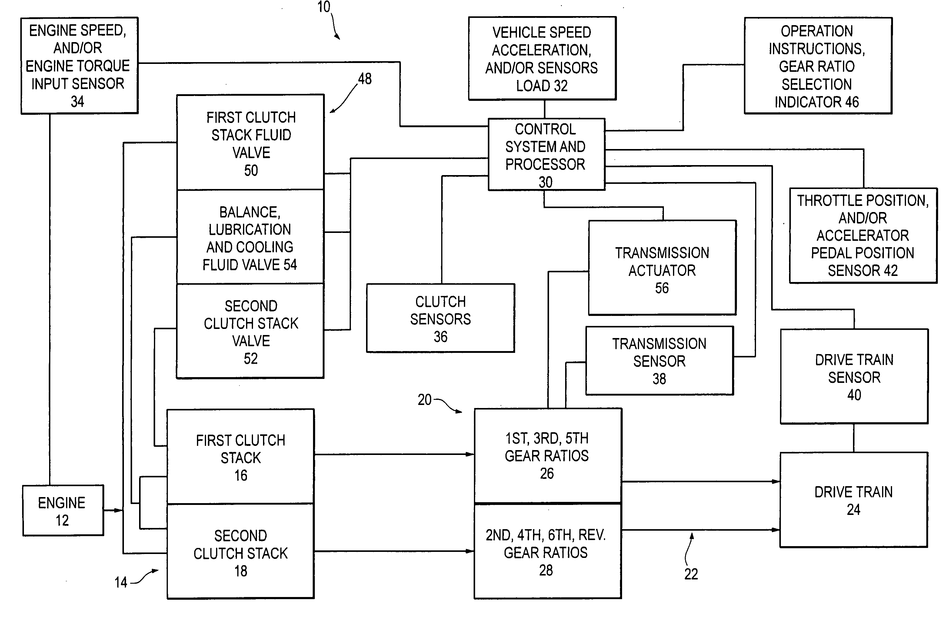
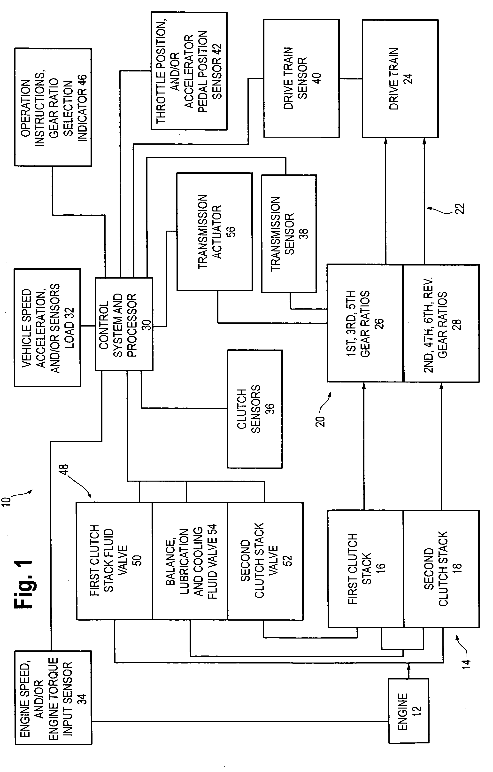
[0040]One example of the invention is illustrated in the block diagram of FIG. 1, for an automotive powertrain system 10. In such a system, a torque input source 12, which in this example is an automotive engine, supplies torque to a multi-clutch system 14 through a drive shaft, torque converter, damping system or other transfer systems. Other torque input sources, such as electric motors, hybrid electric motor and internal combustion engine systems, etc. may be used.

[0041]As used herein, references to “gear ratio” generally shall refer to a system or system element input torque and / or speed relative to the system or system element torque and / or speed output unless otherwise indicated by the usage context. For example, a transmission gear ratio, or transmission gear ratio output refers to the engine torque input to a clutch and transmission system relative to the transmission gear or transmission system output.

[0042]In this example, the multi-clutch system 14 comprises a first clutc...


PUM


Abstract

A transmission system is provided utilizing multiple sets of clutch friction elements, each engaged to transfer torque from a torque input, such as an engine, to different gear ratios. The sets of clutch friction elements are operated simultaneously to provide a blended, gear ratio to a drivetrain. By varying the engagement of the clutch elements, and thus the proportion of the torque transferred to the gear ratio associated with each set of friction elements, an intermediate, effective gear ratio is developed. This effective gear ratio can be increased or decreased in response to external stimuli, such as vehicle and / or engine sensors, by modifying the degree of engagement of each set of clutch friction elements, and thus the proportion of torque transferred by each set of elements to its associated gear ratio.

Description

[0001]This application claims the benefit of Provisional application Ser. No. 60 / 508,922, filed Oct. 6, 2003.FIELD OF THE INVENTION[0002]The invention relates generally to powertrain transmissions utilizing two or more clutch systems, such as those used in automotive multi-clutch transmissions.BACKGROUND[0003]One form of powertrain transmissions utilizes a multiple clutch system to transmit torque from an input source, such as an engine or motor, to a gear box or other gear shifting mechanism, which in turn transfers torque and rotational speed to a drivetrain. Such multi-clutch systems may be used in manual, an assisted manual or automatic transmissions. One type of multi-clutch system is a dual clutch transmission such as those used in automotive applications. Dual clutch transmissions typically are provided with a single torque input from the engine that is transferred by the clutch to one of a pair of shafts out of the clutch to the transmission gear box.[0004]The torque input i...

Claims


Application Information

Patent Timeline
Patent Type & Authority Patents(United States)
IPC IPC(8): F16H3/08F16H3/089B60W10/00F16D25/10F16D48/02F16H3/00F16H61/688
CPCF16H61/688F16H3/006Y10T74/19228F16H2312/02Y10T74/19233F16H2003/0815F16D25/10F16D25/0638
Inventor MCCRARY, PAUL T.BAUER, KARL-HEINZ
Owner BORGWARNER INC
Why Eureka
Try Eureka