Liquid dispensing system

a liquid dispensing system and liquid technology, applied in liquid handling, fluid pressure control, instruments, etc., can solve the problems of increasing the overall increasing the cost of the system, and increasing the cost of the pump. not only expensive, but also known to contribute to contamination

Active Publication Date: 2007-02-06
ADVANCED TECH MATERIALS INC
View PDF8 Cites 108 Cited by
  • Summary
  • Abstract
  • Description
  • Claims
  • Application Information

AI Technical Summary

Benefits of technology

[0025]The liquid dispensing system of the present invention offers several advantages over conventional dispensing systems. For example, because system 10 uses no pumps in the dispense train, liquid 12 will be free of contamination common in conventional systems caused by deterioration of pump components. In addition, liquid 12 is shielded by inner container 20 from the pressurized gas that forces liquid 12 through flow passage 40. This prevents gas from being forced into liquid 12 during the dispensing process, thereby preventing the formation of deleterious microbubbles in liquid 12. Plus, the components of system 10 are relatively inexpensive compared to pumps and other flow control devices, thus reducing the cost of the overall dispensing system. Furthermore, the components of system 10 can easily be integrated into a single, transportable package, which allows for quick and simple connection to the manufacturing process at the end-use facility.

Problems solved by technology

In the manufacture of thin film transistor flat panel displays, the dispensing and delivery of many expensive chemicals is required.
Systems incapable of serving this function necessitate redundant dispense equipment, thereby increasing the overall cost of the system.
These pumps are not only expensive, but also are known to contribute to contamination in the form of bellows and diaphragm shedding, as well as shedding from wear on the pump check valves.
However, the accuracy and flexibility of the amount and speed of chemical dispensed are difficult to maintain.
Further, the drive gas can be forced into the dispensed liquid, thereby causing microbubbles to form in the liquid.
The presence of microbubbles in the deposited liquids may cause defects in the deposited layer or subsequent deposited layers.
However, some dispensing systems using flow control devices have poor stability when a certain amount of liquid must be dispensed in a short period of time.
Also, flow control devices are very expensive, thus adding to the overall cost of the dispense system.

Method used


Image

  • Liquid dispensing system
  • Liquid dispensing system

Examples


Embodiment Construction

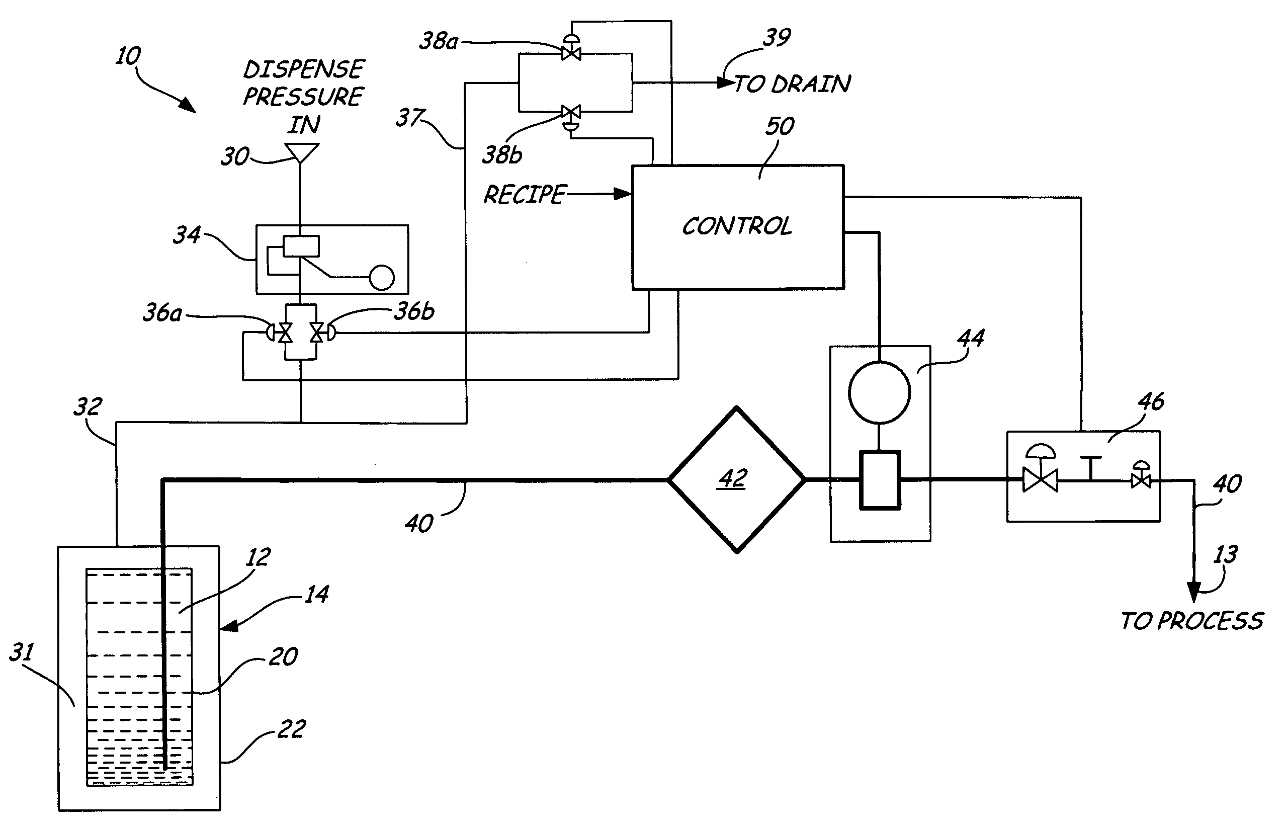
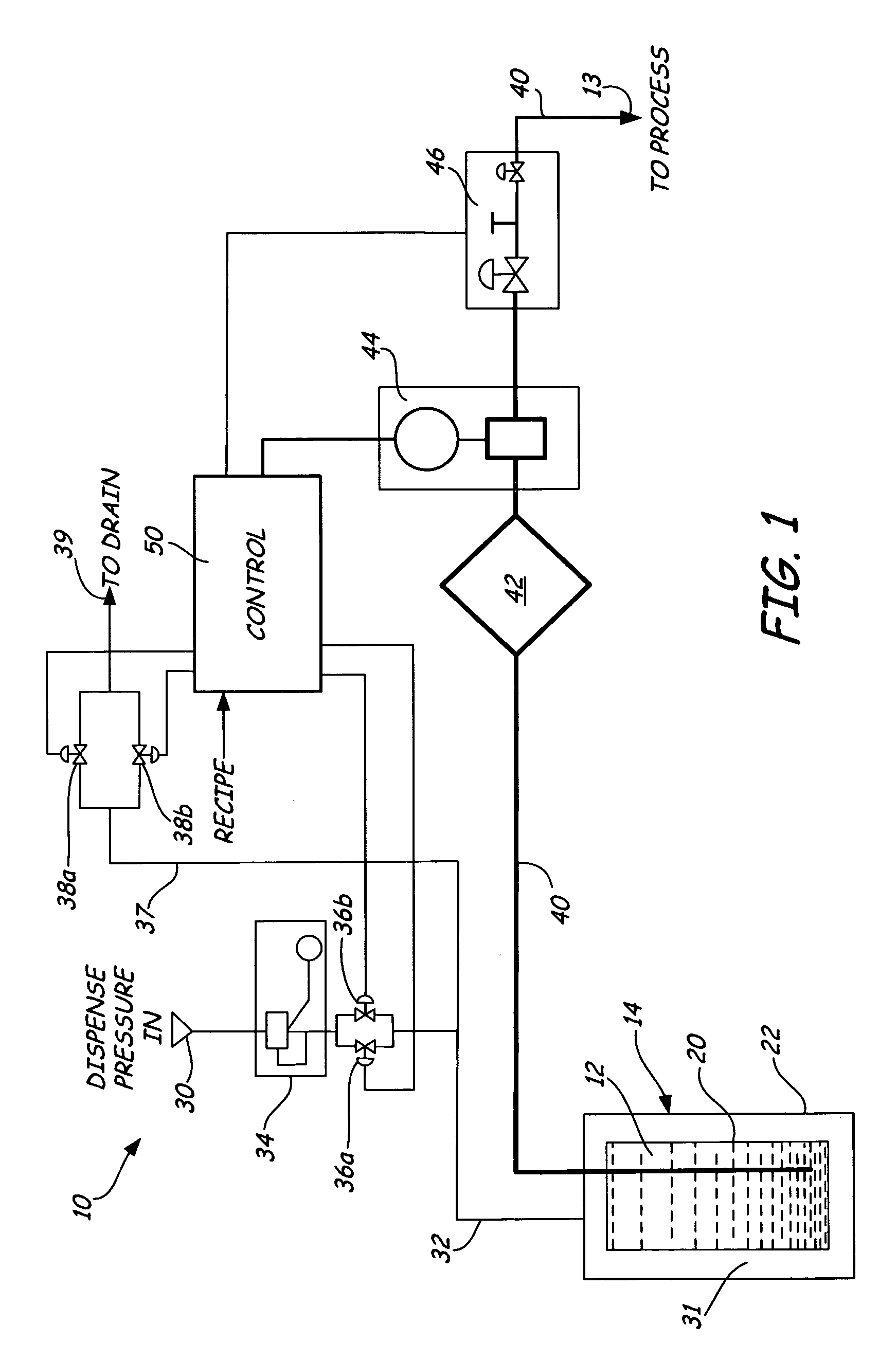
[0011]FIG. 1 is a schematic of liquid dispensing system 10 according to one embodiment of the present invention for dispensing liquid 12 to manufacturing process 13 from container 14. Container 14 includes flexible inner container 20 and rigid outer container 22. System 10 further includes pressurized gas supply 30, pressurized gas passage 32, pressure regulator 34, block valves 36a and 36b, pressure release passage 37, pressure release valves 38a and 38b, pressure release drain 39, flow passage 40, filter 42, pressure transducer 44, stop / suckback valve 46, and controller 50.

[0012]Outer container 22 provides the mechanical support and protection required by flexible inner container 20 (e.g., a flexible polymeric bag or liner) during filling, transport, handling, and dispensing. Outer container 22 is typically constructed of metal, although other materials, including plastic materials, may also be used, depending upon government regulatory specifications for handling of the particula...


PUM


Abstract

A system for dispensing liquid to a manufacturing process from a container including an outer container and a flexible inner container occupied by the liquid. A flow passage provides fluid communication between an interior of the inner container and the manufacturing process. A pressurized fluid source is in fluid communication with a space between inner walls of the outer container and the inner container. The pressurized fluid source causes fluid under pressure to flow into the space between the inner walls of the outer container and the inner container to force liquid out of the inner container to the manufacturing process via the flow passage. A pressure sensor is positioned to sense pressure in the flow passage. A controller responsive to the pressure sensor controls the pressure in the flow passage by modulating the pressure from the pressurized fluid source.

Description

BACKGROUND OF THE INVENTION[0001]The present invention relates to the dispensing and delivery of liquids. In particular, the present invention relates to a system for dispensing liquid that allows for easy control of the volume and speed of liquid dispensed from the same input liquid source.[0002]Certain manufacturing processes require the use of liquid chemicals such as acids, solvents, bases, photoresists, dopants, inorganic solutions, organic solutions, biological solutions, pharmaceuticals, and radioactive chemicals. In many manufacturing process applications, fluid containers are employed as a source of process liquids for liquid delivery systems. Typically, the fluid containers are fabricated and filled at locations remote from the end-use facility. After filling the containers at a filling facility, the containers are typically shipped to the end-use facility, such as for use in a manufacturing process.[0003]At the end-use facility, the fluid container is either incorporated ...

Claims


Application Information

Patent Timeline
Patent Type & Authority Patents(United States)
IPC IPC(8): B65D35/34B67D7/02B67D7/08B67D7/36
CPCG05D16/2013B67D7/0261B65D35/34G01F11/00
Inventor O'DOUGHERTY, KEVIN T.
Owner ADVANCED TECH MATERIALS INC
Why Eureka
Try Eureka