Modular accessory holder

a module and accessory technology, applied in the field of mounting hardware, can solve the problems of difficult removal of such devices for storage, devices susceptible to theft or damage, and devices that are also subject to rapid corrosion, and achieve the effect of reducing relative motion

Inactive Publication Date: 2007-02-06
FUELLING RICHARD A +1
View PDF16 Cites 41 Cited by
  • Summary
  • Abstract
  • Description
  • Claims
  • Application Information

AI Technical Summary

Benefits of technology

[0010]With particular reference to FIG. 4, the present invention comprises a receiver which is permanently mounted to a surface on a boat or other vehicle. The receiver's top surface opens into a vertical slot with tapering side walls. A separate plate slides into this slot. The separate plate has corresponding side walls that mate with the tapering side walls in the receiver. A pair of horizontal steps on the plate come to rest against the receiver's top surface. Although the side walls of the plate rest closely against the side walls of the slot in order to minimize relative motion, the mating of the pair of steps to the receiver's top surface prevents the plate from becoming jammed in the receiver.

Problems solved by technology

Once in position, it is difficult to remove such devices for storage.
This makes the devices susceptible to theft or damage when the boat is left unattended.
In saltwater environments, some of the devices may also be subject to rapid corrosion.
In addition, many accessories are only used sporadically.
The prior art approach typically mounts all these devices in a fixed state, meaning that the boat becomes cluttered with a number of devices that are not actually being used.

Method used


Image

  • Modular accessory holder
  • Modular accessory holder
  • Modular accessory holder

Examples


Embodiment Construction

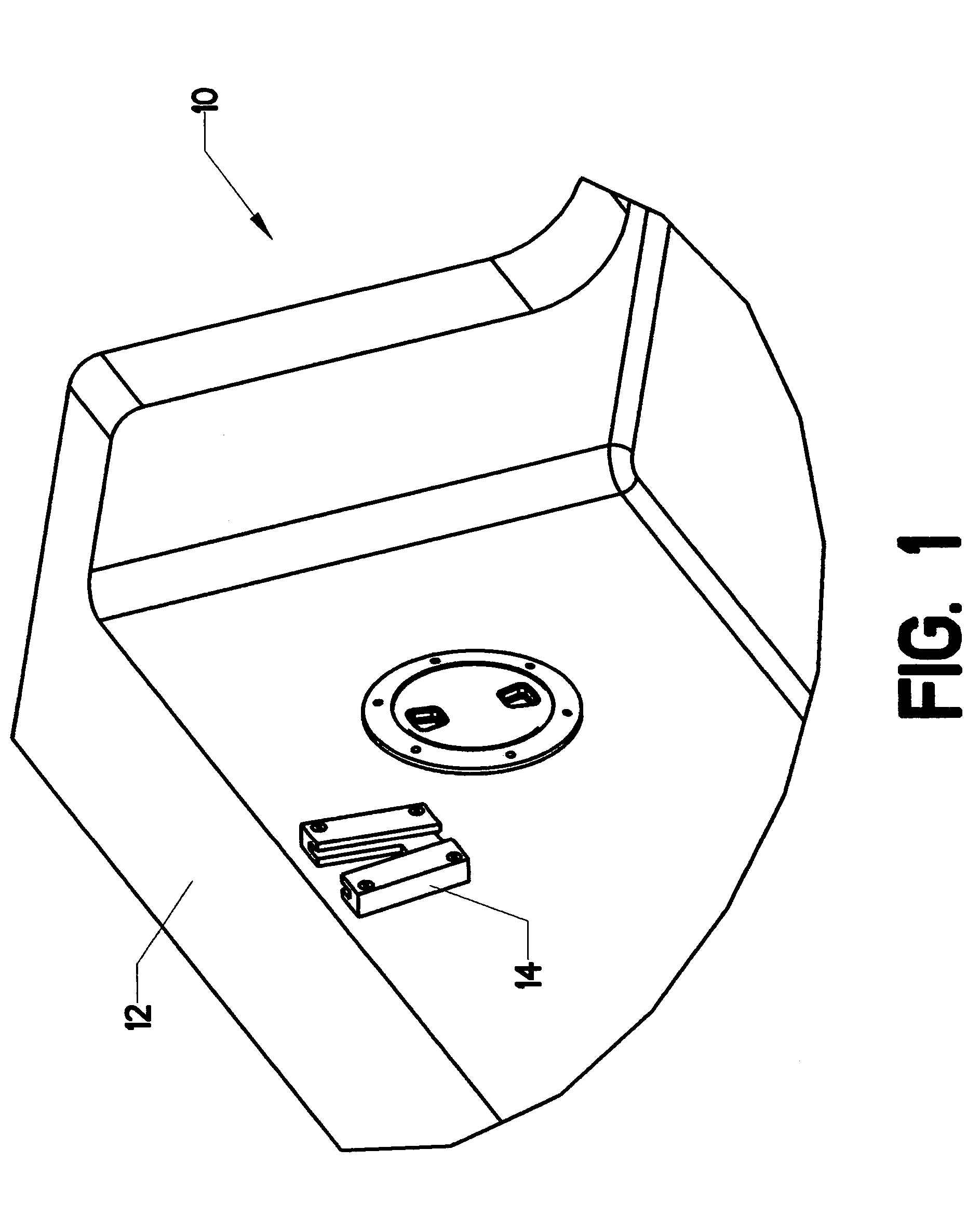
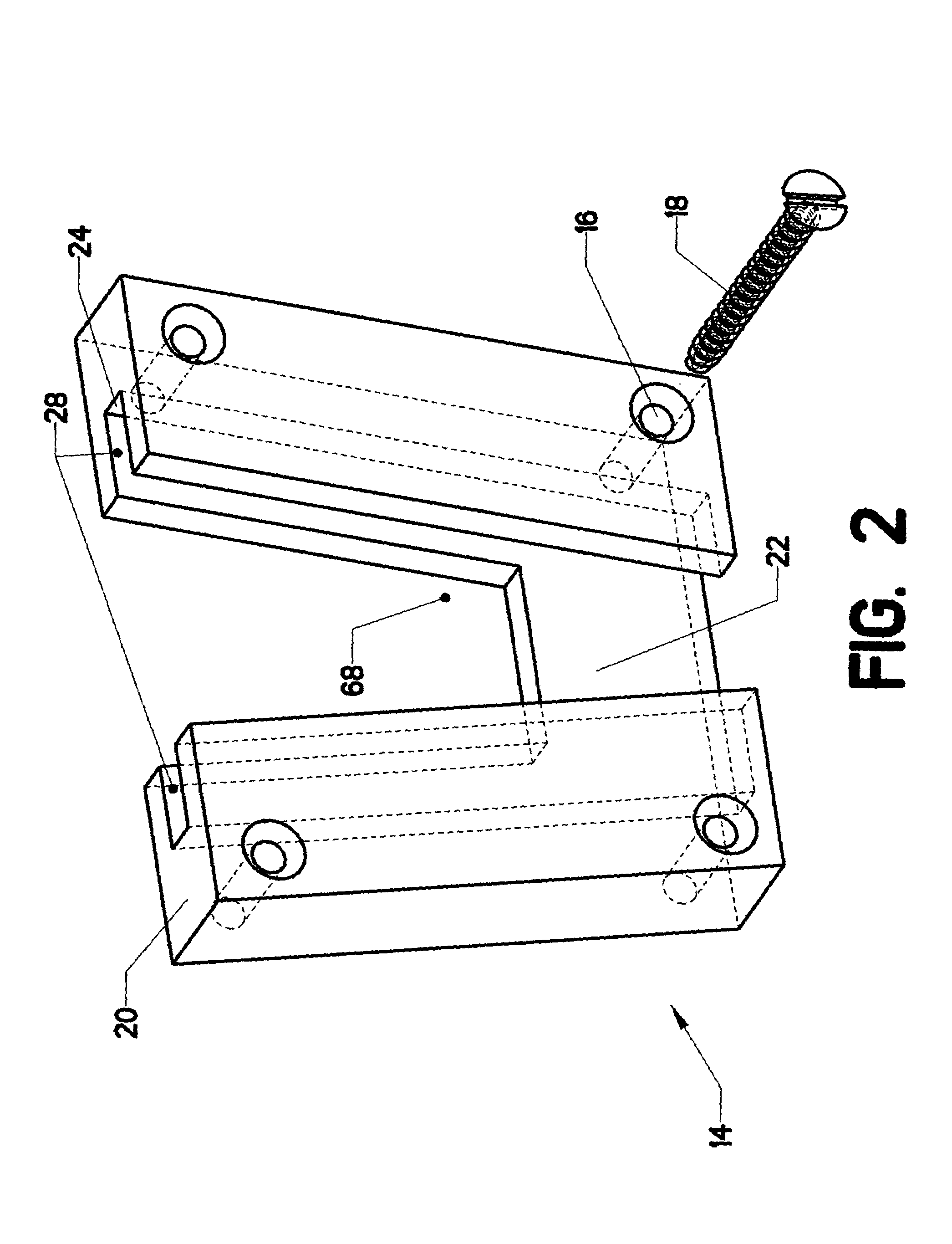
[0023]FIG. 1 shows receiver 14 mounted on gunwale 12 of boat 10. The location of receiver 14 is selected by the user. It typically represents a position where the user needs to mount one or more pieces of equipment. FIG. 2 shows receiver 14 in more detail. It is mounted via passing four fasteners 18 through the four mounting holes 16. Receiver 14 then remains in position.

[0024]Upper surface 20 opens into slot 28, which descends downward. The slot is bounded by a back wall 22, two side walls 24, and a front wall 30 (see FIG. 3). In studying FIGS. 2 and 3, the reader will observe that the two side walls 24 taper inward to form a trapezoidal shape. The forward portion of slot 28 is left open to form open front 68.

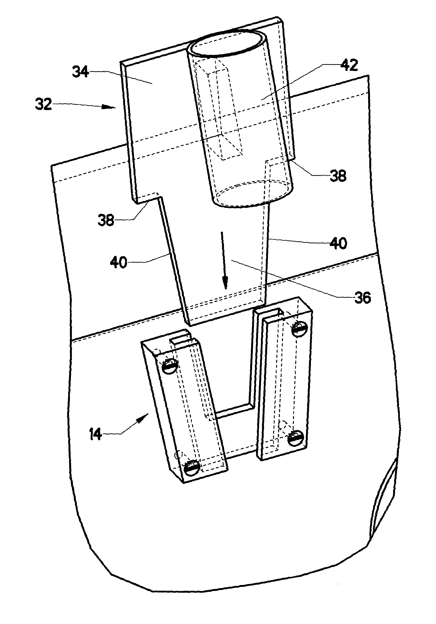
[0025]FIG. 4 shows modular mount 32 ready to be installed in receiver 14. Modular mount 32 consists of plate 34 and a downward-descending tang 36. Two steps 38 are formed at the junction of tang 36 and plate 34. Tang 36 is bounded by a pair of side walls 40. These taper inward...


PUM


Abstract

A receiver and plate for removably mounting devices to a surface on a boat or other vehicle. The receiver's top surface opens into a vertical slot with tapering side walls. The separate plate slides into this slot. The separate plate has corresponding side walls that mate with the tapering side walls in the receiver. A pair of horizontal steps on the plate come to rest against the receiver's top surface. Although the side walls of the plate rest closely against the side walls of the slot in order to minimize relative motion, the mating of the pair of steps to the receiver's top surface prevents the plate from becoming jammed in the receiver. The plate is used as the base member for a variety of holding devices. Different plates can be configured to mount fishing rod holders, lighting masts, navigation equipments, radios, and the like. The user can easily interchange this equipment in a desired position on the boat by removing a plate with a first piece of equipment from the receiver and replacing it with a plate mounting a second piece of equipment. A locking device is optionally provided to lock the plate securely in the receiver.

Description

CROSS-REFERENCES TO RELATED APPLICATIONS[0001]Not applicable.STATEMENT REGARDING FEDERALLY SPONSORED RESEARCH OR DEVELOPMENT[0002]Not Applicable.MICROFICHE APPENDIX[0003]Not ApplicableBACKGROUND OF THE INVENTION[0004]1. Field of the Invention[0005]This invention relates primarily to the field of mounting hardware. More specifically, the invention comprises a receiver attached to a fixed position. A detachable mounting plate can be used to mount fishing rods, lights, radios, and the like to the receiver.[0006]2. Description of the Related Art[0007]A wide variety of equipment is used on fishing and recreational boats. Examples of such equipment include radios, speakers, navigation systems, lights, fishing rod holders, downrigger holders, and similar items. Many of these devices must be attached to the boat in a permanent fashion, such as by using screws. Once in position, it is difficult to remove such devices for storage. This makes the devices susceptible to theft or damage when the...

Claims


Application Information

Patent Timeline
Patent Type & Authority Patents(United States)
IPC IPC(8): A47F5/00A47F7/00F16M13/02
CPCA01K97/10F16M13/02F16M13/00F16M11/14F16M11/041
Inventor FUELLING, RICHARD A.ROWAN, MICHAEL W.
Owner FUELLING RICHARD A
Why Eureka
Try Eureka